Page 4 of 60
IM 817-4
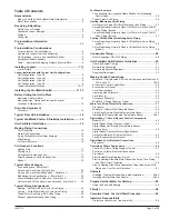
BE = Basic Metasys N2 Open w/o TC w/CO
2
BF = Basic Stand-Alone w/ TC w/CO
2
BG = Basic Stand-Alone Master w/ TC w/CO
2
E1 = Expanded Stand-Alone w/o TC
E2 = Expanded Stand-Alone Master w/o TC
E3 = Expanded Stand-Alone Servant w/o TC
E4 = Expanded BACnet MS/TP w/o TC
E5 = Expanded LonMark SCC w/o TC
E6 = Expanded Metasys N2 Open w/o TC
E7 = Expanded Stand-Alone w/ TC
E8 = Expanded Stand-Alone Master w/ TC
E9 = Expanded Stand-Alone w/o TC w/CO
2
EA = Expanded Stand-Alone Master w/o TC w/CO
2
EB = Expanded Stand-Alone Servant w/o TC w/CO
2
EC = Expanded BACnet MS/TP w/o TC w/CO
2
ED = Expanded LonMark SCC w/o TC w/CO
2
EE = Expanded Metasys N2 Open w/o TC w/CO
2
EF = Expanded Stand-Alone w/ TC w/CO
2
EG = Expanded Stand-Alone Master w/ TC w/CO
2
L1 = Leading Stand-Alone w/o TC
L2 = Leading Stand-Alone Master w/o TC
L3 = Leading Stand-Alone Servant w/o TC
L4 = Leading BACnet MS/TP w/o TC
L5 = Leading LonMark SCC w/o TC
L6 = Leading Metasys N2 Open w/o TC
L7 = Leading Stand-Alone w/ TC
L8 = Leading Stand-Alone Master w/ TC
L9 = Leading Stand-Alone w/o TC w/CO
2
LA = Leading Stand-Alone Master w/o TC w/CO
2
LB = Leading Stand-Alone Servant w/o TC w/CO
2
LC = Leading BACnet MS/TP w/o TC w/CO
2
LD = Leading LonMark SCC w/o TC w/CO
2
LE = Leading Metasys N2 Open w/o TC w/CO
2
LF = Leading Stand-Alone w/ TC w/CO
2
LG = Leading Stand-Alone Master w/ TC w/CO
2
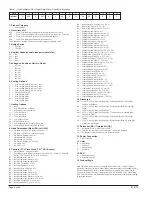
10. Discharge
AB = 21-7/8" Unit, Top Bar Grille Discharge, Full Adapter Back w Closed Pipe
Tunnel w Solid Back
AK = 21-7/8" Unit, Top Bar Grille Discharge, Partial Adapter Back w Open Pipe
Tunnel
AL = 16-5/8" Unit, Top Bar Grille Discharge
AM = 21-7/8" Unit, Top Bar Grille Discharge, 2" Stepdown Full Adapter Back w
Closed Pipe Tunnel
AN = 21-7/8" Unit, Top Bar Grille Discharge, Full Adapter Back w Closed Pipe
Tunnel
AP = 21-7/8" Unit, Top Bar Grille Discharge, Partial Adapter Back w Closed Pipe
Tunnel, Top Duct Intake
11. Return Air (RA) / Outside Air (OA)
22 = RA Bottom Front / OA Rear Duct Collar
24 = 100% RA Bottom Front / No OA Opening / No OA/RA Dampers
30 = RA Bottom Front w Draft Stop / OA Rear Duct Collar
12. Power Connection
G = Box w Switch
13. Color
B = Putty Beige
G = Soft Gray
I = Antique Ivory
W = Off White
14. SKU
B = Standard Delivery
C = Extended Delivery
15. Product Style
1
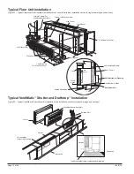
Field-Installed Accessories may accompany Unit Ventilator(s), or may be shipped
separately. These may include: Adapter Backs; Aluminum Louvers; Aluminum Grilles;
Auxiliary Drain Pans; Controls / Sensors; End Panels; Spare Filters; MicroTech II
Controls, Remote Wall Sensors (temperature); End of Cycle DDC Valve; Modulating
DDC Valves; Subbases. See instructions shipped with accessories and install according
to these and the plans.
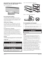
1. Product Category
U = Unit Ventilator
2. Product Identifier*
AVS = Floor, Face and Bypass Damper, Heat/Cool, Heat Only, Cool Only
AVV = Floor, Valve Control, Hydronic or Electric Heat/Cool, Heat Only, Cool Only
AVR = Floor, Valve Control, Hydronic or Electric Reheat/Dehumid
AVB = Floor, Face and Bypass Damper, Hydronic Reheat
* End panels not included; Ordered as accessory, shipped separately boxed
3. Design Series
5 = E Design
6 = F Design
4. Nominal Capacity, cubic feet per minute (cfm)
S07 = 750
S10 = 1000
S13 = 1250
S15 = 1500
5. Voltage, volts, phase, Hertz (v-Hz-ph)
A = 115-60-1
C = 208-60-1
G = 230-60-1
J = 265-60-1
D = 208-60-3
H = 230-60-3
K = 460-60-3
6. Cooling Options
U = 2-row Chilled Water/Hot Water, 2-pipe
D = 3-row Chilled Water/Hot Water, 2-pipe
E = 4-row Chilled Water/Hot Water, 2-pipe
F = 5-row Chilled Water/Hot Water 2-pipe
G = Direct Expansion (DX)
S = 3-row Chilled Water
V = 2-row Chilled Water
W = 4-row Chilled Water
Y = 5-row Chilled Water
7. Heating Options
00 = None
12 = Low Electric Heat, 3-element
13 = High Electric Heat, 6-element
65 = 1-row, Hot Water
66 = 2-row, Hot Water
67 = 3-row, Hot Water
68 = Low Capacity Steam
69 = High Capacity Steam
78 = Low Capacity Steam, Opposite End Drain
79 = High Capacity Steam, Opposite End Drain
8. Hand Orientation [Right (RH) Left (LH)]
A = LH Both Coils (only w Controls by Others)
B = RH Both Coils (only w Controls by Others)
D = RH Electric Heating, One Coil
E = LH Heating, RH Cooling
F = RH Heating, LH Cooling
G = RH Electric Heating, LH Cooling
R = LH Single Coil
S = RH Single Coil
9. Controls (TC = Time Clock, CO
2
= CO
2
Sensor)
23 = Field Mounted Controls by Others
17 = Digital Ready/with Damper Actuators, (3)@ 10k NTC Sensors, 3 Terminal
Strips, 75 VA 24 Volt T’fmr, w/o UV Controller
B1 = Basic Stand-Alone w/o TC
B2 = Basic Stand-Alone Master w/o TC
B3 = Basic Stand-Alone Servant w/o TC
B4 = Basic BACnet MS/TP w/o TC
B5 = Basic LonMark SCC w/o TC
B6 = Basic Metasys N2 Open w/o TC
B7 = Basic Stand-Alone w/ TC
B8 = Basic Stand-Alone Master w/ TC
B9 = Basic Stand-Alone w/o TC w/CO
2
BA = Basic Stand-Alone Master w/o TC w/CO
2
BB = Basic Stand-Alone Servant w/o TC w/CO
2
BC = Basic BACnet MS/TP w/o TC w/CO
2
BD = Basic LonMark SCC w/o TC w/CO
2
Field
1
2
3
4
5
6
7
8
9
10
11
12
13
14
15
Model
U
AVS
6
S07
A
S
65
E
23
AL
22
G
B
C
1
Table 1 - Unit Ventilator (Floor Type) Data Plate - Specific Information


