Page 52 of 60
IM 817-4
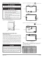
14"
(356mm)
5"
(127 mm)
5" (127 mm)
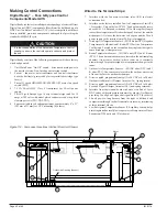
Remove debris, dust, dirt, and
any obstruction from the area
in front of the return air intake
grille at the floor (approximately
3' - see shaded area) as this
will affect unit performance. If
a draftstop system has been
installed be sure that all draftstop
intake grilles are unobstructed.
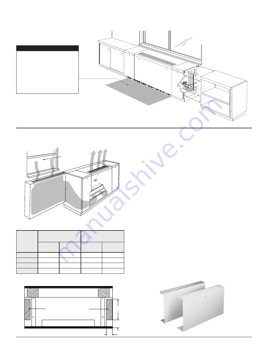
Figure 124 - Cabinet(s) Meeting Unit Ventilator (refer to the
instructions specific to the installation, included with the cabinets).
Draftstop™ System/Window Down-draft Installation
Window down-draft protection is recommended for classrooms where
the following conditions exist:
1.
Window area exceeds 40% of the total outside wall area.
2.
Single-pane glass is used.
3. Outside temperatures are below 35°F for a significant portion of
the occupied period.
The need for window down-draft protection will not always be so
clear cut. Where uncertainty exists, a further check can be made by
calculating the window heat loss at an outdoor temperature of 35°F.
If estimated window heat loss exceeds 250 BTUH/FT, window down-
draft protection is recommended. If estimated window heat loss is less
than 250 Btuh/Ft., the need for down-draft protection is marginal but
should not be arbitrarily dismissed.
The “DraftStop” system can be employed even in those marginal
applications to provide the occupants comfort without the material
installation and operating cost penalty associated with “auxiliary
radiation.” The unit ventilator is ordered with the return air intake
having a draftstop blockoff to restrict return air flow through the front
bottom unit opening, option “30” in field “11” of the model number.
This allows drawing of return air through the draftstop enclosure located
under the windows. A manually adjustable damper is located beneath
each section of DraftStop grille, see figure 128 on page 53. This damper
is provided so that a uniform air velocity can be achieved throughout
the entire length of the DraftStop grille. This simple adjustment is made
once by the installer during the final stage of installation.
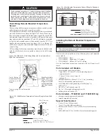
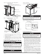
Falling Cold Air
from Window
Figure 125 - DraftStop System Concept
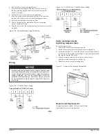
Table 30. DraftStop Grille Length
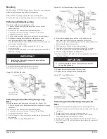
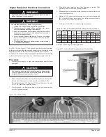
Figure 127 - Typical Finned Radiation Enclosure (left) And Typical
DraftStop Enclosure (right)
Outdoor Air Intake Opening
Figure 126 - Unit Back Showing knockouts for DraftStop Applications
End compartment Draftstop
knockouts must be removed for
proper Draftstop operation.
(21-7/8" units only)
Cabinets
20" High DraftStop
Wall Enclosure
24" High DraftStop
Wall Enclosure or
Storage Cabinets
Unit
Nom.
CFM
Minimum
Length (Ft.)
Each Side
Maximum
Length (Ft.)
Each Side
Minimum
Length (Ft.)
Each Side
Maximum
Length (Ft.)
Each Side
750
1000
1250
1500
3
4
5
6
13
18
22
25
3
4
5
6
22
30
36
42
NOTICE

