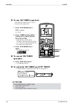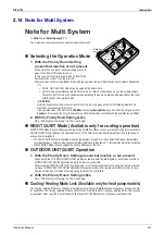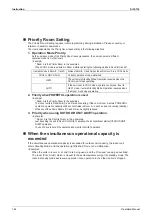
background image

Instruction

Si12-714

142

Operation Manual

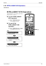
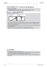
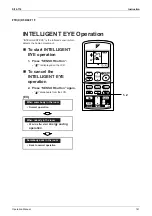
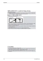
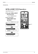
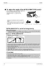
“INTELLIGENT EYE” is useful for Energy Saving.

Notes on “INTELLIGENT EYE”

CAUTION

„

Energy saving operation

• Change the temperature –2

°

C in heating / +2

°

C in cooling / +1

°

C in dry mode from set temperature.

• Decrease the air flow rate slightly in fan operation. (In FAN mode only)

• Application range is as follows.

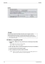
• Sensor may not detect moving objects further than 7m away. (Check the application range)
• Sensor detection sensitivity changes according to indoor unit location, the speed of 

passersby, temperature range, etc.

• The sensor also mistakenly detects pets, sunlight, fluttering curtains and light reflected off of 

mirrors as passersby.

• INTELLIGENT EYE operation will not go on during powerful operation.
• Night set mode will not go on during you use INTELLIGENT EYE operation.

• Do not place large objects near the sensor.

Also keep heating units or humidifiers outside the sensor’s detection area. This sensor can 
detect objects it shouldn’t as well as not detect objects it should.

• Do not hit or violently push the INTELLIGENT EYE sensor. This can lead to damage and 

malfunction.

90˚

55˚

7m

55˚

7m

Vertical angle 90˚
(Side View)

Horizontal angle 110˚
(Top View)

Summary of Contents for B-Series

Page 1: ...Si12 714 Applied Models Inverter Multi Cooling Only Inverter Multi Heat Pump B Series D Series ...

Page 2: ...BVMA8 CDKD25CVMA FWKG25AVM FTKE35BVMA8 CDKD35CVMA FWKG35AVM CDKD50CVMA CDKD60CVMA CDKD25EAVM CDKD35EAVM CDKD25EAVMA CDKD35EAVMA Outdoor Unit 2MKD58DVM 3MKD75BVMA8 3MKD58DVM 4MKD90BVM 3MKD75DVM 4MKD90BVMA 4MKD75DVM 4MKD100DVM zHeat Pump Indoor Unit FTXE25BVMA8 CDXD25CVMA CDXD25EAVMA FLX25AVMA FTXE35BVMA8 CDXD35CVMA CDXD35EAVMA FLX35AVMA FTXD50FVM CDXD50CVMA FLX50AVMA8 FTXD60FVM CDXD60CVMA FLX60AVMA...

Page 3: ...oor Units 49 Part 4 Function and Control 55 1 Main Functions 56 1 1 Frequency Principle 56 1 2 Power Airflow Dual Flaps Wide Angle Louvers and Auto Swing 58 1 3 Fan Speed Control for Indoor Units 59 1 4 Programme Dry Function 60 1 5 Automatic Operation 61 1 6 Thermostat Control 62 1 7 Night Set Mode 63 1 8 ECONO Mode 64 1 9 MOLD PROOF Operation 64 1 10 INTELLIGENT EYE 65 1 11 HOME LEAVE Operation ...

Page 4: ...5 2 10 MOLD PROOF Operation 136 2 11 HOME LEAVE Operation 137 2 12 INTELLIGENT EYE Operation 139 2 13 TIMER Operation 145 2 14 Note for Multi System 147 2 15 Care and Cleaning 149 2 16 Troubleshooting 166 Part 6 Service Diagnosis 169 1 Caution for Diagnosis 170 1 1 Troubleshooting with Operation Lamp 170 2 Problem Symptoms and Measures 172 3 Service Check Function 173 4 Code Indication on the Remo...

Page 5: ...1 3 Removal of PCB 251 1 4 Removal of Fan Motor 257 1 5 Removal of Coils Thermistors 259 1 6 Removal of Reactor 265 1 7 Removal of Sound Blanket 266 1 8 Removal of Compressor 269 2 Outdoor Unit 80 90 Class 271 2 1 Removal of Outer Panels 271 2 2 Removal of Propeller Fans 274 2 3 Removal of Electrical Box 275 2 4 Removal of PCB 282 2 5 Removal of Fan Motor 285 2 6 Removal of Electronic Expansion Va...

Page 6: ...roller 312 1 2 Jumper Settings 313 1 3 Application of Silicon Grease to a Power Transistor and a Diode Bridge 315 Part 9 Appendix 317 1 Piping Diagrams 318 1 1 Indoor Units 318 1 2 Outdoor Units 324 2 Wiring Diagrams 328 2 1 Indoor Units 328 2 2 Outdoor Units 331 Index i Drawings Flow Charts v ...

Page 7: ...er cable plug from the plug socket before disassembling the equipment for repair Working on the equipment that is connected to the power supply may cause an electrical shook If it is necessary to supply power to the equipment to conduct the repair or inspecting the circuits do not touch any electrically charged sections of the equipment If the refrigerant gas is discharged during the repair work d...

Page 8: ...trical shock Do not clean the air conditioner by splashing water Washing the unit with water may cause an electrical shock Be sure to provide the grounding when repairing the equipment in a humid or wet place to avoid electrical shocks Be sure to turn off the power switch and unplug the power cable when cleaning the equipment The internal fan rotates at a high speed and cause injury Be sure to con...

Page 9: ...heat generation or fire When wiring between the indoor and outdoor units make sure that the terminal cover does not lift off or dismount because of the cable If the cover is not mounted properly the terminal connection section may cause an electrical shock excessive heat generation or fire Do not damage or modify the power cable Damaged or modified power cable may cause an electrical shock or fire...

Page 10: ...ent children from swallowing it If a child swallows the coin battery see a doctor immediately Warning Caution Installation of a leakage breaker is necessary in some cases depending on the conditions of the installation site to prevent electrical shocks Do not install the equipment in a place where there is a possibility of combustible gas leaks If the combustible gas leaks and remains around the u...

Page 11: ... to install the packing and seal on the installation frame properly If the packing and seal are not installed properly water may enter the room and wet the furniture and floor For unitary type only Caution Icon Type of Information Description Note Note A note provides information that is not indispensable but may nevertheless be valuable to the reader such as tips and tricks Caution Caution A caut...

Page 12: ...Si12 714 List of Functions 1 Part 1 List of Functions 1 List of Functions 2 1 1 Cooling Only 2 1 2 Heat Pump 9 ...

Page 13: ...urability Auto Restart after Power Failure 3 D Airflow Self Diagnosis Digital LED Display Comfort Airflow Mode Wiring Error Check 3 Step Airflow H P Only Anticorrosion Treatment of Outdoor Heat Exchanger Comfort Control Auto Fan Speed Flexibility Multi Split Split Type Compatible Indoor Unit Indoor Unit Quiet Operation Flexible Voltage Correspondence Night Quiet Mode Automatic High Ceiling Applica...

Page 14: ...Auto Restart after Power Failure 3 D Airflow Self Diagnosis Digital LED Display Comfort Airflow Mode Wiring Error Check 3 Step Airflow H P Only Anticorrosion Treatment of Outdoor Heat Exchanger Comfort Control Auto Fan Speed Flexibility Multi Split Split Type Compatible Indoor Unit Indoor Unit Quiet Operation Flexible Voltage Correspondence Night Quiet Mode Automatic High Ceiling Application Outdo...

Page 15: ...tart after Power Failure 3 D Airflow Self Diagnosis Digital LED Display Comfort Airflow Mode Wiring Error Check 3 Step Airflow H P Only Anticorrosion Treatment of Outdoor Heat Exchanger Comfort Control Auto Fan Speed Flexibility Multi Split Split Type Compatible Indoor Unit Indoor Unit Quiet Operation Flexible Voltage Correspondence Night Quiet Mode Automatic High Ceiling Application Outdoor Unit ...

Page 16: ...estart after Power Failure 3 D Airflow Self Diagnosis Digital LED Display Comfort Airflow Mode Wiring Error Check 3 Step Airflow H P Only Anticorrosion Treatment of Outdoor Heat Exchanger Comfort Control Auto Fan Speed Flexibility Multi Split Split Type Compatible Indoor Unit Indoor Unit Quiet Operation Flexible Voltage Correspondence Night Quiet Mode Automatic High Ceiling Application Outdoor Uni...

Page 17: ...ility Durability Auto Restart after Power Failure Comfort Airflow Mode Self Diagnosis Digital LED Display 3 Step Airflow H P Only Wiring Error Check Comfort Control Auto Fan Speed Anticorrosion Treatment of Outdoor Heat Exchanger Indoor Unit Quiet Operation Night Quiet Mode Automatic Flexibility Multi Split Split Type Compatible Indoor Unit Outdoor Unit Quiet Operation Manual Flexible Voltage Corr...

Page 18: ...lity Auto Restart after Power Failure 3 D Airflow Self Diagnosis Digital LED Display Comfort Airflow Mode Wiring Error Check 3 Step Airflow H P Only Anticorrosion Treatment of Outdoor Heat Exchanger Comfort Control Auto Fan Speed Flexibility Multi Split Split Type Compatible Indoor Unit Indoor Unit Quiet Operation Flexible Voltage Correspondence Night Quiet Mode Automatic High Ceiling Application ...

Page 19: ...eliability Durability Auto Restart after Power Failure 3 D Airflow Self Diagnosis Digital LED Display 3 Step Airflow H P Only Wiring Error Check Comfort Control Auto Fan Speed Anticorrosion Treatment of Outdoor Heat Exchanger Indoor Unit Quiet Operation Flexibility Multi Split Split Type Compatible Indoor Unit Night Quiet Mode Automatic Flexible Voltage Correspondence Outdoor Unit Quiet Operation ...

Page 20: ...Free Reliability Durability Auto Restart after Power Failure 3 D Airflow Self Diagnosis Digital LED Display 3 Step Airflow H P Only Wiring Error Check Comfort Control Auto Fan Speed Anticorrosion Treatment of Outdoor Heat Exchanger Indoor Unit Quiet Operation Flexibility Multi Split Split Type Compatible Indoor Unit Night Quiet Mode Automatic Flexible Voltage Correspondence Outdoor Unit Quiet Oper...

Page 21: ...eliability Durability Auto Restart after Power Failure 3 D Airflow Self Diagnosis Digital LED Display 3 Step Airflow H P Only Wiring Error Check Comfort Control Auto Fan Speed Anticorrosion Treatment of Outdoor Heat Exchanger Indoor Unit Quiet Operation Flexibility Multi Split Split Type Compatible Indoor Unit Night Quiet Mode Automatic Flexible Voltage Correspondence Outdoor Unit Quiet Operation ...

Page 22: ...iability Durability Auto Restart after Power Failure 3 D Airflow Self Diagnosis Digital LED Display 3 Step Airflow H P Only Wiring Error Check Comfort Control Auto Fan Speed Anticorrosion Treatment of Outdoor Heat Exchanger Indoor Unit Quiet Operation Flexibility Multi Split Split Type Compatible Indoor Unit Night Quiet Mode Automatic Flexible Voltage Correspondence Outdoor Unit Quiet Operation Ma...

Page 23: ...ability Auto Restart after Power Failure 3 D Airflow Self Diagnosis Digital LED Display 3 Step Airflow H P Only Wiring Error Check Comfort Control Auto Fan Speed Anticorrosion Treatment of Outdoor Heat Exchanger Indoor Unit Quiet Operation Flexibility Multi Split Split Type Compatible Indoor Unit Night Quiet Mode Automatic Flexible Voltage Correspondence Outdoor Unit Quiet Operation Manual High Ce...

Page 24: ...Si12 714 Specifications 13 Part 2 Specifications 1 Specifications 14 1 1 Indoor Units Cooling Only 14 1 2 Outdoor Units Cooling Only 22 1 3 Indoor Units Heat Pump 28 1 4 Outdoor Units Heat Pump 33 ...

Page 25: ...29 26 Heat Insulation Both Liquid and Gas Pipes Both Liquid and Gas Pipes Piping Connection Liquid mm φ 6 4 φ 6 4 Gas mm φ 9 5 φ12 7 Drain mm φ18 0 φ18 0 Drawing No 3D049308A 3D049309A Model FTKE25BVM FTKE35BVM Rated Capacity 2 5kW Class 3 5kW Class Front Panel Color White White Air Flow Rates m min cfm H 7 8 275 7 7 272 M 6 4 226 6 3 222 L 5 0 177 4 9 173 SL 4 3 152 4 4 155 Fan Type Cross Flow Fa...

Page 26: ...Liquid and Gas Pipes Piping Connection Liquid mm φ 6 4 φ 6 4 Gas mm φ 9 5 φ12 7 Drain mm φ18 0 φ18 0 Drawing No 3D047557 3D047558 Model FTKD50FVM FTKD60FVM Rated Capacity 5 0kW Class 6 0kW Class Front Panel Color White White Air Flow Rates m min cfm H 16 8 593 17 5 618 M 14 0 494 14 6 516 L 11 8 417 12 2 431 SL 10 4 367 10 8 381 Fan Type Cross Flow Fan Cross Flow Fan Motor Output W 43 43 Speed Ste...

Page 27: ... Air Filter Removable Washable Mildew Proof Running Current Rated A 0 23 0 22 0 21 0 23 0 22 Power Consumption Rated W 50 Power Factor 98 8 98 8 99 2 98 8 98 8 Temperature Control Microcomputer Control Dimensions H W D mm 290 1 050 238 Packaged Dimensions H W D mm 337 1 147 366 Weight kg 12 Gross Weight kg 17 Operation Sound H M L SL dBA 46 42 37 34 Heat Insulation Both Liquid and Gas Pipes Piping...

Page 28: ... Static Pressure Pa 40 40 Moisture Removal L h 1 2 1 9 Heat Insulation Both Liquid and Gas Pipes Both Liquid and Gas Pipes Piping Connection Liquid mm φ 6 4 φ 6 4 Gas mm φ 9 5 φ12 7 Drain mm VP20 O D φ 26 I D φ 20 VP20 O D φ 26 I D φ 20 Drawing No 3D046077A 3D046078A Model CDKD50CVM CDKD60CVM Rated Capacity 5 0kW Class 6 0kW Class Front Panel Color Air Flow Rates m min cfm H 12 0 424 16 0 565 M 11...

Page 29: ...essure Pa 40 40 Moisture Removal L h 1 2 1 9 Heat Insulation Both Liquid and Gas Pipes Both Liquid and Gas Pipes Piping Connection Liquid mm φ 6 4 φ 6 4 Gas mm φ 9 5 φ12 7 Drain mm VP20 O D φ 26 I D φ 20 VP20 O D φ 26 I D φ 20 Drawing No 3D046073A 3D046074A Model CDKD50CVMA CDKD60CVMA Rated Capacity 5 0kW Class 6 0kW Class Front Panel Color Air Flow Rates m min cfm H 12 0 424 16 0 565 M 11 0 388 1...

Page 30: ...atic Pressure Pa 35 35 Moisture Removal L h 1 2 1 9 Heat Insulation Both Liquid and Gas Pipes Both Liquid and Gas Pipes Piping Connection Liquid mm φ 6 4 φ 6 4 Gas mm φ 9 5 φ12 7 Drain mm VP20 O D φ 26 I D φ 20 VP20 O D φ 26 I D φ 20 Drawing No 3D052111 3D052112 Model CDKD25EAVMA CDKD35EAVMA Rated Capacity 2 5kW Class 3 5kW Class Front Panel Color Air Flow Rates m min cfm H 8 7 307 8 7 307 M 8 0 2...

Page 31: ...Gas Pipes Piping Connection Liquid mm φ 6 4 φ 6 4 Gas mm φ 9 5 φ12 7 Drain mm φ18 0 φ18 0 Drawing No 3D036717 3D036718 Model FLK50AVMA8 FLK60AVMA8 Rated Capacity 5 0W Class 5 7kW Class Front Panel Color Almond White Almond White Air Flow Rates m min cfm H 11 4 402 12 0 424 M 10 0 353 10 6 374 L 8 5 300 9 3 328 SL 7 5 265 8 3 293 Fan Type Sirocco Fan Sirocco Fan Motor Output W 34 34 Speed Steps 5 S...

Page 32: ...le Washable Mildew Proof Long life Removable Washable Mildew Proof Long life Running Current Rated A 0 18 0 18 Power Consumption Rated W 40 40 Power Factor 96 6 96 6 Temperature Control Microcomputer Control Microcomputer Control Dimensions H W D mm 332 787 191 332 787 191 Packaged Dimensions H W D mm 250 1 003 409 250 1 003 409 Weight kg 11 5 11 5 Gross Weight kg 16 16 Operation Sound H M L SL dB...

Page 33: ...ting Current A 6 9 6 5 Dimensions H W D mm 735 936 300 735 936 300 Packaged Dimensions H W D mm 784 960 357 784 960 357 Weight kg 55 55 Gross Weight kg 59 59 Operation Sound dBA 46 46 Piping Connection Liquid mm φ 6 4 2 φ 6 4 3 Gas mm φ12 7 2 φ12 7 3 Drain mm φ16 0 φ16 0 Heat Insulation Both Liquid and Gas Pipes Both Liquid and Gas Pipes No of Wiring Connection 3 for Power Supply 4 for Interunit W...

Page 34: ...ons H W D mm 735 936 300 735 936 300 Packaged Dimensions H W D mm 784 960 357 784 960 357 Weight kg 58 58 Gross Weight kg 62 62 Operation Sound dBA 48 48 Piping Connection Liquid mm φ 6 4 1 φ 9 5 2 φ 6 4 2 φ 9 5 2 Gas mm φ12 7 1 φ15 9 2 φ12 7 2 φ15 9 2 Drain mm φ16 0 φ16 0 Heat Insulation Both Liquid and Gas Pipes Both Liquid and Gas Pipes No of Wiring Connection 3 for Power Supply 4 for Interunit...

Page 35: ...Power Consumption W H 107 L 99 Starting Current A 15 9 Dimensions H W D mm 770 900 320 Packaged Dimensions H W D mm 900 925 390 Weight kg 68 Gross Weight kg 75 Operation Sound dBA 54 Piping Connection Liquid mm φ 6 4 2 φ 9 5 2 Gas mm φ12 7 2 φ15 9 2 Drain mm φ25 0 Heat Insulation Both Liquid and Gas Pipes No of Wiring Connection 3 for Power Supply 4 for Interunit Wiring Max Piping Length m 70 for ...

Page 36: ...wer Consumption W H 68 L 46 Starting Current A 9 4 Dimensions H W D mm 735 936 300 Packaged Dimensions H W D mm 784 960 357 Weight kg 58 Gross Weight kg 62 Operation Sound dBA 48 Piping Connection Liquid mm φ 6 4 1 φ 9 5 2 Gas mm φ12 7 1 φ15 9 2 Drain mm φ16 0 Heat Insulation Both Liquid and Gas Pipes No of Wiring Connection 3 for Power Supply 4 for Interunit Wiring Max Interunit Piping Length m 6...

Page 37: ...4 Power Consumption W H 60 L 41 Starting Current A 12 1 Dimensions H W D mm 908 900 320 Packaged Dimensions H W D mm 942 926 394 Weight kg 66 Gross Weight kg 77 Operation Sound dBA 48 Piping Connection Liquid mm φ 6 4 2 φ 9 5 2 Gas mm φ12 7 1 φ15 9 3 Drain mm φ25 0 Heat Insulation Both Liquid and Gas Pipes No of Wiring Connection 3 for Power Supply 4 for Interunit Wiring Max Piping Length m 70 for...

Page 38: ...er Consumption W H 60 L 41 Starting Current A 12 1 Dimensions H W D mm 908 900 320 Packaged Dimensions H W D mm 942 926 394 Weight kg 66 Gross Weight kg 77 Operation Sound dBA 48 Piping Connection Liquid mm φ 6 4 2 φ 9 5 2 Gas mm φ12 7 1 φ15 9 3 Drain mm φ 25 0 Heat Insulation Both Liquid and Gas Pipes No of Wiring Connection 3 for Power Supply 4 for Interunit Wiring Max Interunit Piping Length m ...

Page 39: ...as Pipes Both Liquid and Gas Pipes Piping Connection Liquid mm φ 6 4 φ 6 4 Gas mm φ 9 5 φ12 7 Drain mm φ18 0 φ18 0 Drawing No 3D047553 3D047554 Model FTXD50FVM FTXD60FVM Cooling Heating Cooling Heating Rated Capacity 5 0kW Class 6 0kW Class Front Panel Color White White Air Flow Rates m min cfm H 16 8 593 17 5 618 17 5 618 18 7 660 M 14 0 494 14 9 526 14 6 516 16 1 569 L 11 8 417 12 5 441 12 2 431...

Page 40: ...lter Removable Washable Mildew Proof Running Current Rated A 0 23 0 22 0 21 0 23 0 22 0 23 0 22 0 21 0 23 0 22 Power Consumption Rated W 50 50 Power Factor 98 8 98 8 99 2 98 8 98 8 98 8 98 8 99 2 98 8 98 8 Temperature Control Microcomputer Control Dimensions H W D mm 290 1 050 238 Packaged Dimensions H W D mm 337 1 147 366 Weight kg 12 Gross Weight kg 17 Operation Sound H M L SL dBA 46 42 37 34 46...

Page 41: ...tic Pressure Pa 40 40 Moisture Removal L h 1 2 1 9 Heat Insulation Both Liquid and Gas Pipes Both Liquid and Gas Pipes Piping Connection Liquid mm φ 6 4 φ 6 4 Gas mm φ 9 5 φ12 7 Drain mm VP20 O D φ 26 I D φ 20 VP20 O D φ 26 I D φ 20 Drawing No 3D046069A 3D046070A Model CDXD50CVMA CDXD60CVMA Cooling Heating Cooling Heating Rated Capacity 5 0kW Class 6 0kW Class Front Panel Color Air Flow Rates m mi...

Page 42: ...eps Quiet Auto 5 Steps Quiet Auto Running Current Rated A 0 47 0 48 0 49 0 52 0 53 0 47 0 48 0 49 0 52 0 53 0 47 0 48 0 49 0 52 0 53 0 47 0 48 0 49 0 52 0 53 Power Consumption Rated W 70 71 72 72 73 70 71 72 72 73 70 71 72 72 73 70 71 72 72 73 Power Factor 67 7 64 3 61 2 62 9 59 9 67 7 64 3 61 2 62 9 59 9 67 7 64 3 61 2 62 9 59 9 67 7 64 3 61 2 62 9 59 9 Temperature Control Microcomputer Control M...

Page 43: ...s Pipes Piping Connection Liquid mm φ 6 4 φ 6 4 Gas mm φ 9 5 φ12 7 Drain mm φ18 0 φ18 0 Drawing No 3D036690 3D036691 Model FLX50AVMA8 FLX60AVMA8 Cooling Heating Cooling Heating Rated Capacity 5 0kW Class 5 7kW Class Front Panel Color Almond White Almond White Air Flow Rates m min cfm H 11 4 402 12 1 427 12 0 424 12 8 452 M 10 0 353 9 8 346 10 6 374 10 6 374 L 8 5 300 7 5 265 9 3 328 8 4 297 SL 7 5...

Page 44: ...rent A 10 1 10 2 Dimensions H W D mm 735 936 300 908 900 320 Packaged Dimensions H W D mm 784 960 357 942 926 394 Weight kg 59 73 Gross Weight kg 63 80 Operation Sound dBA 48 49 48 49 Piping Connection Liquid mm φ 6 4 3 φ 6 4 3 φ 9 5 1 Gas mm φ12 7 2 φ15 9 1 φ 9 5 1 φ12 7 1 φ15 9 2 Drain mm φ16 0 φ 25 0 Heat Insulation Both Liquid and Gas Pipes Both Liquid and Gas Pipes No of Wiring Connection 3 f...

Page 45: ...Specifications Si12 714 34 Specifications ...

Page 46: ...gram 35 Part 3 Printed Circuit Board Connector Wiring Diagram 1 Printed Circuit Board Connector Wiring Diagram 36 1 1 Wall Mounted Type 36 1 2 Duct Connected Type 42 1 3 Floor Ceiling Suspended Dual Type 44 1 4 Wall Built in Type 47 1 5 Outdoor Units 49 ...

Page 47: ...or for centralized control HA 5 S26 Connector for display PCB 6 S28 Connector for signal receiver PCB 7 S32 Connector for heat exchanger thermistor 8 S35 Connector for INTELLIGENT EYE sensor PCB 1 S29 Connector for control PCB 1 S27 Connector for control PCB 1 S36 Connector for control PCB 1 V1 Varistor 2 JA Address setting jumper JB Fan speed setting when compressor is OFF on thermostat JC Power ...

Page 48: ...rcuit Board Connector Wiring Diagram 37 PCB Detail PCB 1 Control PCB indoor unit PCB 4 INTELLIGENT EYE sensor PCB V1 FU1 S1 S6 S7 S26 S28 S32 JC JB JA LED A S35 S21 R4779 PCB 2 Signal Receiver PCB PCB 3 Display PCB S29 R4289 RTH1 SW1 S27 LED3 LED2 LED1 R4290 S36 R4547 ...

Page 49: ...ized control to 5 rooms 5 S26 Connector for signal receiver PCB 6 S32 Connector for heat exchanger thermistor 7 S35 Connector for INTELLIGENT EYE Sensor PCB 1 S27 Connector for control PCB 1 S36 Connector for control PCB 1 V1 Varistor 2 JA Address setting jumper JB Fan speed setting when compressor is OFF on thermostat JC Power failure recovery function Refer to page 313 for more detail 3 LED A LE...

Page 50: ...12 714 Printed Circuit Board Connector Wiring Diagram Printed Circuit Board Connector Wiring Diagram 39 PCB Detail PCB 1 Control PCB indoor unit PCB 2 Signal Receiver PCB PCB 3 INTELLIGENT EYE Sensor PCB ...

Page 51: ...A 5 S26 Connector for buzzer PCB 6 S28 Connector for signal receiver PCB 7 S32 Connector for heat exchanger thermistor 8 S35 Connector for Intelligent Eye sensor PCB 1 S29 Connector for control PCB 1 S27 Connector for control PCB 2 S38 Connector for display PCB 1 S37 Connector for buzzer PCB 1 S36 Connector for control PCB 1 V1 Varistor 2 JA Address setting jumper JB Fan speed setting when compres...

Page 52: ...ector Wiring Diagram 41 PCB Detail PCB 1 Control PCB indoor unit PCB 2 Signal Receiver PCB PCB 3 Buzzer PCB PCB 4 Display PCB PCB 5 INTELLIGENT EYE sensor PCB S1 V1 FU1 S6 S8 S26 R2860 S28 S32 JC JB JA LED A S21 S35 SW1 S29 R2861 R2862 RTH1 S38 S27 LED1 LED2 LED3 S37 R2863 S36 R2864 ...

Page 53: ...ntrol to 5 rooms 4 S26 Connector for display PCB 5 S32 Connector for heat exchanger thermistor 1 S1 Connector for control PCB 1 V1 Varistor 2 JA Address setting jumper JB Fan speed setting when compressor is OFF on thermostat JC Power failure recovery function Refer to page 313 for more detail 3 LED A LED for service monitor green 4 FU1 Fuse 3 15A 1 SW1 S1W Forced operation ON OFF switch 2 LED1 LE...

Page 54: ...Si12 714 Printed Circuit Board Connector Wiring Diagram Printed Circuit Board Connector Wiring Diagram 43 PCB Detail PCB 2 Display PCB ...

Page 55: ...tor for display PCB 5 S26 Connector for signal receiver PCB 6 S32 Connector for heat exchanger thermistor 7 S37 Connector for power supply PCB 1 S36 Connector for control PCB 1 S25 Connector for control PCB 1 S27 Connector for control PCB 2 S31 Connector for room temperature thermistor 1 JA Address setting jumper JB Fan speed setting when compressor is OFF on thermostat JC Power failure recovery f...

Page 56: ...Si12 714 Printed Circuit Board Connector Wiring Diagram Printed Circuit Board Connector Wiring Diagram 45 PCB Detail PCB 1 Control PCB indoor unit PCB Detail PCB 2 Power Supply PCB ...

Page 57: ...Board Connector Wiring Diagram Si12 714 46 Printed Circuit Board Connector Wiring Diagram PCB 3 Display PCB PCB 4 Signal Receiver PCB SW1 S27 PbF PHOTO 2P084377 1 SW1 I RTH WLU 3 C1 C2 C3 EX511 REV 12 S27 R6057 S31 RTH ...

Page 58: ...for AC fan motor 4 S21 Connector for centralized control to 5 rooms 5 S26 Connector for signal receiver PCB 6 S32 Connector for heat exchanger thermistor 1 S27 Connector for control PCB 1 V1 Varistor 2 JA Address setting jumper JB Fan speed setting when compressor is OFF on thermostat JC Power failure recovery function Refer to page 313 for more detail 3 LED A LED for service monitor green 4 FU1 F...

Page 59: ...Printed Circuit Board Connector Wiring Diagram Si12 714 48 Printed Circuit Board Connector Wiring Diagram PCB Detail PCB 1 Control PCB indoor unit PCB 2 Signal Receiver PCB ...

Page 60: ...tor PCB 11 S71 Connector for S72 on inverter PCB MID2 12 S80 Connector for four way valve 13 S90 Connector for thermistor outdoor air heat exchanger and discharge pipe 14 S91 Connector for fin thermistor 15 S92 Connector for gas pipe thermistor 16 S93 Connector for liquid pipe thermistor 17 S101 Connector for S102 on service monitor PCB 1 S52 Connector for S51 on control PCB 2 S102 Connector for S...

Page 61: ...agram MID1 Inverter PCB MID2 PCB Detail 2MKD58DVM 3MKD58 75DVM 4MKD75DVM Control PCB outdoor unit Service Monitor PCB 1 V3 Varistor 2 FU1 Fuse 30A 1 FU201 Fuse 3 15A R6044 S32 S33 S71 S31 S80 S101 S51 S10 S23 S22 S21 S20 S40 S91 S93 S92 S90 LED4 LED2 LED A S52 S102 LED3 LED1 SW4 SW3 SW1 SW5 SW2 R6045 ...

Page 62: ...d Connector Wiring Diagram 51 PCB Detail 3MKD75BVMA8 4MKD90BVM 4MKD90BVMA 3MXD68BVMA8 4MXD80BVMA Control PCB outdoor unit Service Monitor PCB R6046 S32 S33 S71 S31 S80 S101 S51 S10 S23 S22 S21 S20 S40 S91 S93 S92 S90 LED4 LED2 LED A S52 S102 LED3 LED1 SW4 SW3 SW1 SW5 SW2 R6047 ...

Page 63: ...14 52 Printed Circuit Board Connector Wiring Diagram PCB Detail 4MKD100DVM Control PCB outdoor unit Service Monitor PCB R4901 S32 S33 S71 S31 S80 S101 S51 S10 S23 S22 S21 S20 S40 S91 S93 S92 S90 LED4 LED2 LED A S52 S102 LED3 LED1 SW4 SW3 SW1 SW5 SW2 R4911 ...

Page 64: ...ed Circuit Board Connector Wiring Diagram Printed Circuit Board Connector Wiring Diagram 53 PCB Detail All Outdoor Units MID1 Inverter PCB MID2 SPM R4019 V3 FU1 S11 S34 S72 S70 FU201 3 15A R4020 R4021 CN14 CN11 L1 L2 ...

Page 65: ...Printed Circuit Board Connector Wiring Diagram Si12 714 54 Printed Circuit Board Connector Wiring Diagram ...

Page 66: ...68 1 13 Other Functions 69 2 Function of Main Structural Parts 71 2 1 Main Structural Parts 71 2 2 Function of Thermistor 72 3 Control Specification 76 3 1 Mode Hierarchy 76 3 2 Frequency Control 77 3 3 Controls at Mode Changing Start up 80 3 4 Discharge Pipe Temperature Control 81 3 5 Input Current Control 81 3 6 Freeze up Protection Control 82 3 7 Heating Peak cut Control 82 3 8 Fan Control 83 3...

Page 67: ...e explains the conversion principle Drawing of Inverter The following drawing shows a schematic view of the inverter principle Phase Description 1 The supplied AC power source is converted into the DC power source for the present 2 The DC power source is reconverted into the three phase AC power source with variable frequency When the frequency increases the rotation speed of the compressor increa...

Page 68: ...air condition with a small room temperature variation Energy saving heating and cooling Once the set temperature is reached the energy saving operation enables to maintain the room temperature at low power Frequency Limits The following table shows the functions that define the minimum and maximum frequency Forced Cooling Heating Operation For more information refer to Forced operation mode on pag...

Page 69: ...ge of airflow that guarantees a comfortable air distribution Auto Swing In case of FTKD20 35D The following table explains the auto swing process for heating cooling dry and fan 3 D Airflow Wall Mounted Type 50 71 Class Alternative repetition of vertical and horizontal swing motions enables uniform air conditioning of the entire room This function is effective for starting the air conditioner When...

Page 70: ... rate is automatically controlled when the FAN setting button is set to automatic Note 1 During powerful operation fan rotates at H tap 50 90 rpm 2 Fan stops during defrost operation Automatic Air Flow Control for Heating On heating mode the indoor fan speed will be regulated according to the indoor heat exchanger temperature and the difference between the room temperature and the required set poi...

Page 71: ... room temperature at startup and the temperature set by the microcomputer is divided into two zones Then the unit operates in the dry mode with an appropriate capacity for each zone to maintain the temperature and humidity at a comfortable level Room temperature at startup Set temperature X Thermostat OFF point Y Thermostat ON point Z 24ºC or more Room temperature at startup X 2 5ºC X 0 5ºC or Y 0...

Page 72: ... C 2 Main unit setting temperature equals remote controller setting temperature 3 Operation ON OFF point and mode switching point are as follows Heating Cooling switching point Room temperature Main unit setting temperature 2 5 deg Cooling Heating switching point Room temperature Main unit setting temperature 2 5 deg Thermostat ON OFF point is the same as the ON OFF point of cooling or heating ope...

Page 73: ...in any zones except A The monitoring time has passed while the temperature difference is in the zone B Cooling Dry 10 minutes Heating 10 seconds Cooling Dry Wall Mounted Type Floor Ceiling suspended Type Duct Connected Type Heating Wall Mounted Type Floor Ceiling suspended Type Duct Connected Type B A OFF ON C Cooling 0 5 C Dry 0 5 C Room temperature setpoint Cooling 2 0 C Dry 2 5 2 0 C R4668 B A ...

Page 74: ... heating or cooling the room at the set temperature for the first one hour then automatically raises the temperature setting slightly in the case of cooling or lowers it slightly in the case of heating for economical operations This prevents excessive heating in winter and excessive cooling in summer to ensure comfortable sleeping conditions and also conserves electricity Cooling Operation In case...

Page 75: ... The latest command has the priority Details ECONO mode can be activated while the unit is running The remote controller can send the ECONO command when the unit is in COOL HEAT DRY or AUTO operation When the ECONO command is valid the upper limit of frequency is restricted 1 9 MOLD PROOF Operation FTKD25 35D MOLD PROOF operation is a function which reduces the spread of mold by using Fan mode to ...

Page 76: ...mputer doesn t have a signal from the sensor in 20 minutes it judges that nobody is in the room and operates the unit in temperature shifted 2 C from the set temperature Cooling Dry 2 C higher Heating 2 C lower and Auto according to the operation mode at that time 1 In case of Fan mode the fan speed reduces by 50 rpm If the sensor detects the outputs 10 times sec or more it judges humans exist 1se...

Page 77: ...es so as to prevent this phenomena After this 40 minutes the prohibition of the thermostat off is cancelled and it can realize the conditions to conduct thermostat off depending on the room temperature In or after this 40 minutes if the sensor detects human motion detection signal it let the set temperature and the fan speed return to the original set point keeping a normal operation Others The dr...

Page 78: ...ed the function becomes effective when the operation is started If this button is pressed in powerful operation the powerful operation is reset and this function becomes effective The HOME LEAVE button is ineffective in dry mode and fan mode 2 Details of Function A mark representing HOME LEAVE is indicated on the liquid crystal display of the remote controller The indoor unit is operated according...

Page 79: ...ty minutes In case of FTKD25 35D Ex POWERFUL operation in cooling mode Operation mode Fan speed Target set temperature COOL H tap 50 rpm 18 C DRY Dry rotating speed 50 rpm Normally targeted temperature in dry operation Approx 2 C HEAT H tap 50 rpm 30 C FAN H tap 50 rpm AUTO Same as cooling heating in POWERFUL operation The target is kept unchanged R7096 Target temp Fan 50rpm Set temp 18 C POWERFUL...

Page 80: ...mode refers to the following table In the case of multi system operation there are times when the unit does not activate with this button Forced operation mode Forced operation mode will be set by pressing the ON OFF button for between 5 to 9 sec while the unit is not operating Note When the ON OFF button is pressed for 10 sec or more the operation will be stopped See page 90 for the detail of For...

Page 81: ...o air condition large living rooms The filter can be used for approximately 3 years if periodic maintenance is performed 1 13 8 Mold Proof Air Filter Prefiter For FTKD25 35D FTK X D50 71F FTK X E25 35B FLK X 25 60A The filter net is treated with mold resisting agent TBZ harmless colorless and odorless Due to this treatment the amount of mold growth is much smaller than that of normal filters 1 13 ...

Page 82: ...Main Structural Parts 2 1 Main Structural Parts Heat Pump Model Cooling Only Model Note Expansion Valve In Case of 2MK X EVA B 3MK X EVA C 4MK X EVA D Four way valve Compressor Solenoid valve EVB EVC EVD EVA Expansion valve R4595 SV D Compressor EVB EVC EVD EVA Expansion valve R4596 ...

Page 83: ...emperature becomes lower than the outdoor heat exchanger temperature the discharge pipe thermistor is judged as disconnected B Discharge Pipe Thermistor 1 The discharge pipe thermistor is used for controlling temperature of the discharge pipe If the temperature of discharge pipe used in place of the inner temperature of the compressor rises abnormally the operating frequency drops or the operation...

Page 84: ...mes lower than the indoor heat exchanger temperature the discharge pipe thermistor is judged as disconnected The indoor heat exchanger thermistors are also used for preventing abnormal high pressure 5 The indoor heat exchanger thermistors are used for detecting incorrect wiring During checking incorrect wiring refrigerant is passed in order from the port A to detect a heat exchanger temperature an...

Page 85: ...pipe temperature becomes lower than the outdoor heat exchanger temperature the discharge pipe thermistor is judged as disconnected B Discharge Pipe Thermistor 1 The discharge pipe thermistor is used for controlling temperature of the discharge pipe If the temperature of discharge pipe used in place of the inner temperature of the compressor rises abnormally the operating frequency drops or the ope...

Page 86: ...ezing During the cooling operation if the temperature drops abnormally the operating frequency becomes lower then the operation halts 3 The indoor heat exchanger thermistors are used for anti icing control During the cooling operation if the heat exchanger temperature in the room where operation is halted becomes 1 C or if the room temperature heat exchanger temperature in the room where operation...

Page 87: ...eration Determine Operating Mode Judge the operating mode command set by each room in accordance with the instructing procedure and determine the operating mode of the system The following procedure will be taken as the modes conflict with each other 1 The system will follow the mode determined first First push first set 2 For the rooms set with different mode select stand by mode Operation lamp f...

Page 88: ...et a minimum value as an upper limit frequency among the frequency upper limits of the following functions Compressor protection input current discharge pipes Low Hz high pressure peak cutting freeze up protection defrost 3 Determine lower limit frequency Set a maximum value as an lower limit frequency among the frequency lower limits of the following functions Four way valve operating compensatio...

Page 89: ...ncy must be initialized according to the total of a maximum D value of each room and a total value of Q ΣQ of the operating room the room in which the thermostat is set to ON Q value Indoor unit output determined from indoor unit volume air flow rate and other factors PI Control Determine Frequency Up Down by D Signal 1 P control Calculate a total of the D value in each sampling time 20 seconds an...

Page 90: ... lower limit Frequency management is carried out only when the frequency rises 5 Upper and lower limit of frequency by PI control The frequency upper and lower limits are set depending on the total of S values of a room When low noise commands come from the indoor unit more than one room or when outdoor unit low noise or quiet commands come from all the rooms the upper limit frequency must be lowe...

Page 91: ...rried out after the operation stopped Detail The OFF delay of four way valve Energize the coil for 150 sec after unit operation is stopped 3 3 3 Four Way Valve Operation Compensation Outline Heat Pump Only At the beginning of the operation as the four way valve is switched acquire the differential pressure required for activating the four way valve by having output the operating frequency which is...

Page 92: ...r rushing on the stop zone the compressor operation stops If a drooping current is continues for 1 0 second after rushing on the drooping zone the frequency will be 2 Hz drooping Repeating the above drooping continues until the current rushes on the drooping zone without change In the keep zone the frequency limit will remain In the return reset zone the frequency limit will be cancelled Limitatio...

Page 93: ...Heating Peak cut Control Outline Heat Pump Only During heating operation the signals being sent form the indoor unit allow the operating frequency limitation and prevent abnormal high pressure The signal from the indoor unit must be divided as follows Detail Conditions for Start Controlling Judge the controlling start with the indoor heat exchanger temperature after 2 min from operation start and ...

Page 94: ...OFF for 30 seconds Tap Control in Indoor Outdoor Unit Quiet Operation 1 When Cooling Operation When the outdoor air temperature is less than 37 C the fan tap must be set to L 2 When Heating Operation When the outdoor air temperature is more than 4 C the fan tap must be turned to L only for heat pump model 3 9 Liquid Compression Protection Function 2 Outline In order to obtain the dependability of ...

Page 95: ... the operation or ending the defrosting Conditions for Canceling Defrost The target heat exchanger temperature as the canceling condition is selected in the range of 4 C Te 12 C according to the air temperature as the following formula The target heat exchanger temperature 45 65 ambient temperature 14 The defrost operation surely operates in 120 seconds after the start A B After then the defrost o...

Page 96: ...ectronic expansion valve is fully closed when turning on the power 2 Pressure equalizing control Room Distribution Control 1 Gas pipe isothermal control distribution control in cooling 2 SC control distribution control in heating Open Control 1 Electronic expansion valve control when starting operation 2 Control when frequency changed 3 Control for defrosting only for heat pump model 4 Oil recover...

Page 97: ...e equalizing control Gas pipe isothermal control SC control only for heat pump model Control when frequency changed Control for abnormally high discharge pipe temperature Liquid pipe temperature control for stopped rooms Dew prevention control for indoor rotor Oil recovery control Indoor freeze up protection control Liquid pipe temperature control When power is turned ON Cooling 1 room operation C...

Page 98: ...e gas pipe temperature the average gas pipe temperature open the electronic expansion valve in that room When the gas pipe temperature the average gas pipe temperature close the electronic expansion valve in that room 3 12 5 SC Control Outline Heat Pump Only Detect the temperature of liquid pipe and heat exchanger of the rooms and compensate the electronic expansion valve opening so that the SC of...

Page 99: ...em should be down 3 12 8 Control when frequency is changed When the target pipe temperature control is active if the target frequency is changed for a specified value in a certain time period cancel the target discharge pipe temperature control and change the opening of the target electronic expansion valve according to the shift 3 12 9 High Temperature of the Discharge Pipe When the compressor is...

Page 100: ...3 13 3 Insufficient Gas Control Outline If a power consumption is below the specified value in which the frequency is higher than the specified frequency it must be regarded as gas insufficient In addition to such conventional function if the discharge temperature is higher than the target discharge pipe temperature and more than the specified temperature and the electronic expansion valve is full...

Page 101: ...abnormal but the indoor unit which is not in the freezing prohibiting zone is present in more than 1 room 1 The indoor unit is not abnormal The indoor unit which is not in the peak cut prohibited zone is present in more than 1 room 2 The outdoor unit is not abnormal and not in the 3 minute stand by mode 3 The operating mode of the outdoor unit is the stop mode 4 The slide selection switch of the f...

Page 102: ... indoor unit heat exchanger thermistor is disconnected An indoor unit is in trouble if a trouble occurs during the wiring error checking Emergency stop Any of the LED indicators 1 4 stays on Note 1 It takes about 10 15 minutes after pressing the wiring error check switch to complete the checking Wrong wiring between the upper and lower units cannot be self corrected 2 Wrongly connected liquid and ...

Page 103: ...ced operation is over LED1 Room A wiring LED2 Room B wiring 1st flashing LED Port A piping 2nd flashing LED Port B piping The first stay on LED means the room that is connected with Port A The next stay on LED means the one connected with Port B Example Let s suppose the LED indicators are flashing as follows The above means that Port A is connected with Port B and Port B with Room A or self corre...

Page 104: ...oom can be set as the priority room Control start conditions Priority room setting is made AND Powerful signal from the priority room unit is received Note The operation mode of the priority room unit has precedence Cancellation of control The control function is canceled when the Powerful operation mode is switched off or 20 minutes elapse after Powerful Operation started 3 16 3 POWERFUL Operatio...

Page 105: ...ing to only heat H Short circuit pins 1 and 3 of the connector S15 Setting to only cool C short circuit pins 3 and 5 of the connector S15 The following specifications apply to the connector housing and pins JST products Housing VHR 5N Pin SVH 21T 1 1 Note that forced operation is also possible in COOL HEAT mode COOL mode C HEAT mode H 5 C 3 H 1 R1397 ...

Page 106: ... 2 4 Preparation Before Operation 118 2 5 AUTO DRY COOL HEAT FAN Operation 121 2 6 Adjusting the Air Flow Direction 123 2 7 POWERFUL Operation 133 2 8 OUTDOOR UNIT QUIET Operation 134 2 9 ECONO Operation 135 2 10 MOLD PROOF Operation 136 2 11 HOME LEAVE Operation 137 2 12 INTELLIGENT EYE Operation 139 2 13 TIMER Operation 145 2 14 Note for Multi System 147 2 15 Care and Cleaning 149 2 16 Troublesh...

Page 107: ...o know a clever method of using it In order to meet this expectation of the users giving sufficient explanations taking enough time can be said to reduce about 80 of the requests for servicing However good the installation work is and however good the functions are the customer may blame either the room air conditioner or its installation work because of improper handling The installation work and...

Page 108: ...nd Cleaning 149 155 152 Trouble Shooting Troubleshooting 166 166 166 Drawing No 3P194550 5 3P098590 1H 3P194537 6 3P192025 2 Model Series Duct Connected Type Floor Ceiling Suspended Dual Type Wall Built in Type CDK X D25 60C CDK X D25 35E FLK X 25 60A FWKG25 35A Read before Operation Safety Precautions 98 98 98 98 Names of Parts 109 109 112 115 Preparation before Operation 118 118 118 118 Operatio...

Page 109: ... attempt to install the air conditioner by your self Incorrect work will result in water leakage electric shocks or fire For installation consult the dealer or a qualified technician In order to avoid electric shock fire or injury if you detect any abnormally such as smell of fire stop the operation and turn off the breaker And call your dealer for instructions CAUTION The air conditioner must be ...

Page 110: ...r small animals which can enter the unit Once in the unit such animals can cause malfunc tions smoke or fire when making contact with electrical parts Do not operate the air conditioner with wet hands Do not wash the indoor unit with excessive water only use a slightly wet cloth Do not place things such as vessels containing water or anything else on top of the unit Water may pene trate into the u...

Page 111: ...Instruction Si12 714 100 Operation Manual 2 3 Names of Parts FTKD 25 35 D Indoor Unit ON OFF 16 14 13 15 12 1 3 4 5 7 9 10 11 8 6 2 Names of parts ...

Page 112: ... switch once to start operation Push once again to stop it The operation mode refers to the following table This switch is useful when the remote controller is missing 13 Operation lamp green 14 TIMER lamp yellow 15 INTELLIGENT EYE lamp green 16 Signal receiver It receives signals from the remote controller When the unit receives a signal you will hear a short beep Operation start beep beep Settin...

Page 113: ...p it 7 MODE selector button It selects the operation mode DRY COOL FAN 8 QUIET button OUTDOOR UNIT QUIET operation 9 FAN setting button It selects the air flow rate setting 10 SWING button Adjusting the Air Flow Direction 11 MOLD PROOF button MOLD PROOF operation 12 SENSOR button INTELLIGENT EYE operation 13 ON TIMER button 14 OFF TIMER button 15 TIMER Setting button It changes the time setting 16...

Page 114: ...Si12 714 Instruction Operation Manual 103 FTK X D 50 60 71 F Names of parts Indoor Unit 1 2 4 3 10 11 9 7 8 15 12 13 14 16 6 5 ...

Page 115: ...lamp red Lights up when you use HOME LEAVE Operation 15 Indoor Unit ON OFF switch Push this switch once to start operation Push once again to stop it The operation mode refer to the following table This switch is useful when the remote controller is missing 16 Signal receiver It receives signals from the remote controller When the unit receives a signal you will hear a short beep Operation start b...

Page 116: ...tart operation Press once again to stop it 7 MODE selector button It selects the operation mode AUTO DRY COOL HEAT FAN 8 QUIET button OUTDOOR UNIT QUIET operation 9 FAN setting button It selects the air flow rate setting 10 SENSOR button INTELLIGENT EYE operation 11 SWING button Flap Horizontal blade 12 SWING button Louver Vertical blades 13 ON TIMER button 14 OFF TIMER button 15 TIMER Setting but...

Page 117: ...Instruction Si12 714 106 Operation Manual FTK X E 25 35 B Names of parts Indoor Unit ON OFF 1 3 4 5 6 7 9 10 11 2 14 15 16 8 12 13 ...

Page 118: ...once to start operation Push once again to stop it The operation mode refers to the following table This switch is useful when the remote controller is missing 13 Operation lamp green 14 TIMER lamp Yellow 15 HOME LEAVE lamp red 16 Signal receiver It receives signals from the remote controller When the unit receives a signal you will hear a short beep Operation start beep beep Settings changed beep...

Page 119: ...eration Press once again to stop it 7 MODE selector button It selects the operation mode AUTO DRY COOL HEAT FAN 8 QUIET button for OUTDOOR UNIT QUIET operation Only works for multi connection 9 FAN setting button It selects the air flow rate setting 10 SWING button 11 SENSOR button for INTELLIGENT EYE operation 12 ON TIMER button 13 OFF TIMER button 14 TIMER Setting button It changes the time sett...

Page 120: ...Si12 714 Instruction Operation Manual 109 CDK X D 25 35 50 60 C CDK X D 25 35 E Names of parts Indoor Unit 3 6 8 9 10 7 1 4 5 2 ...

Page 121: ...ration lamp green 8 TIMER lamp yellow 9 HOME LEAVE lamp red LIghts up when you use HOME LEAVE operation 10 Indoor Unit ON OFF switch Push this switch once to start operation Push once again to stop it This switch is useful when the remote controller is missing The operation mode refers to the following table Outdoor Unit 11 Air inlet Back and side 12 Refrigerant piping and inter unit cable 13 Drai...

Page 122: ...hanges the temperature setting 6 ON OFF button Press this button once to start operation Press once again to stop it 7 MODE selector button It selects the operation mode AUTO DRY COOL HEAT FAN 8 QUIET button OUTDOOR UNIT QUIET operation 9 FAN setting button It selects the air flow rate setting 10 ON TIMER button 11 OFF TIMER button 12 TIMER Setting button It changes the time setting 13 TIMER CANCE...

Page 123: ... ceiling or to a wall The descriptions contained in this manual show the case when installation is being carried out to the ceiling The methods of operation used are the same when installing to a wall CAUTION Before opening the front grille be sure to stop the operation and turn the breaker OFF O N OFF 1 2 3 4 5 6 11 12 10 7 9 8 13 14 ...

Page 124: ... operation Push once again to stop it 2 Push the switch using an object with a sharp tip such as a pen 2 This switch is useful when the remote controller is missing 14 Signal receiver 2 It receives signals from the remote controller 2 When the unit receives a signal you will hear a short beep 2 Operation start beep beep 2 Settings changed beep 2 Operation stop beeeeep 2 The operation mode refers t...

Page 125: ... OFF button Press this button once to start operation Press once again to stop it 7 MODE selector button It selects the operation mode AUTO DRY COOL HEAT FAN 8 QUIET button OUTDOOR UNIT QUIET operation 9 FAN setting button It selects the air flow rate setting 10 SWING button 11 ON TIMER button 12 OFF TIMER button 13 TIMER Setting button It changes the time setting 14 TIMER CANCEL button It cancels...

Page 126: ...ilter Front grille Louvers vertical blades Air outlet It is inside this part Flaps horizontal blades Air inlet Back and side Air outlet Refrigerant piping and inter unit cable Drain hose Earth terminal It is inside of this part Air Purifying Filter with Photocatalytic Deodori zing Function Outside air temperature sensor It senses the ambient temperature around the unit ...

Page 127: ...it If you touch those parts this may cause an injury Display and Operation part Operation lamp green Timer lamp yellow A part which re ceives signals from remote controller When a signal is received an opera tion lamp blinks simultaneously with receiving sound and the reception can be checked Operation start beep beep Setting change beep Operation stop beeeeeep Receiving part Hole for temperature ...

Page 128: ...ature setting 6 ON OFF button Press this button once to start operation Press once again to stop it 7 MODE selector button It selects the operation mode DRY COOL FAN 8 SILENT button for OUTDOOR UNIT SILENT operation 9 FAN setting button It selects the air flow rate setting 10 ON TIMER button 11 OFF TIMER button 12 TIMER Setting button It changes the time setting 13 TIMER CANCEL button It cancels t...

Page 129: ... type and replace the two old batteries together When the system is not used for a long time take the batteries out We recommend replacing once a year although if the remote controller display begins to fade or if reception deteriorates please replace with new alkali batteries Using manganese batteries reduces the lifespan The attached batteries are provided for the initial use of the system The u...

Page 130: ...ch the unit 2 Fix the holder to a wall a pillar etc with the screws supplied with the holder 3 Place the remote controller in the remote controller holder ATTENTION About remote controller Never expose the remote controller to direct sunlight Dust on the signal transmitter or receiver will reduce the sensitivity Wipe off dust with soft cloth Signal communication may be disabled if an electronic st...

Page 131: ...for a long period for example in spring or autumn turn the breaker OFF Use the air conditioner in the following conditions Operation outside this humidity or temperature range may cause a safety device to disable the system C ON OFF POWERFUL HOME LEAVE MODE FAN SWING QUIET SENSOR TEMP 1 3 2 Recommended temperature setting For cooling 26 C 28 C For heating 20 C 24 C Mode Operating conditions If ope...

Page 132: ...ssing of the button advances the mode setting in sequence AUTO DRY COOL HEAT FAN 2 Press ON OFF button The OPERATION lamp lights up To stop operation 3 Press ON OFF button again Then OPERATION lamp goes off To change the temperature setting 4 Press TEMPERATURE adjustment button DRY or FAN mode AUTO or COOL or HEAT mode The temperature setting is not variable Press to raise the temperature and pres...

Page 133: ...ir around all parts of the room After the start of heating operation it takes some time before the room gets warmer In heating operation frost may occur on the outdoor unit and lower the heating capacity In that case the system switches into defrosting operation to take away the frost During defrosting operation hot air does not flow out of indoor unit Note on DRY operation The computer chip works...

Page 134: ...to increase your com fort To adjust the horizontal blades flaps 1 Press SWING button is displayed on the LCD and the flaps will begin to swing 2 When the flaps have reached the desired position press SWING button once more The display will go blank The flaps will stop moving TEMP ON OFF POWERFUL MODE FAN SWING QUIET SENSOR ECONO MOLDPROOF TIMER ON CANCEL OFF 1 2 ...

Page 135: ...ing range depends on the operation mode See the figure If the unit is operated after being stopped with the flaps pointed down in cooling or dry operation the flaps will automatically move to a horizontal position after about one hour to prevent condensation from forming on them ATTENTION Always use a remote controller to adjust the flaps angle If you attempt to move it forcibly with hand when it ...

Page 136: ...ed on the LCD and the flaps will begin to swing 2 When the flap has reached the desired position press SWING button once more The flap will stop moving disappears from the LCD To adjust the vertical blades louvers 3 Press SWING button is displayed on the LCD 4 When the louvers have reached the desired position press the SWING button once more The louvers will stop moving disappears from the LCD TI...

Page 137: ...ng range depends on the operation mode See the figure Three Dimensional 3 D Airflow Using three dimensional airflow circulates cold air which tends to collected at the bottom of the room and hot air which tends to collect near the ceiling throughout the room preventing areas of cold and hot developing ATTENTION Always use a remote controller to adjust the flaps angle If you attempt to move it forc...

Page 138: ...ase your com fort To adjust the horizontal blades flaps 1 Press SWING button The display will light up and the flaps will begin to swing 2 When the flaps have reached the desired position press SWING button once more The display will go blank The flaps will stop moving C TEMP ON OFF POWERFUL HOME LEAVE MODE FAN SWING QUIET SENSOR O N 1 2 ...

Page 139: ...on the operation mode See the figure ATTENTION Always use a remote controller to adjust the flaps angle If you attempt to move it forcibly with hand when it is swinging the mechanism may be broken Be careful when adjusting the louvres Inside the air outlet a fan is rotating at a high speed In DRY mode or COOL mode In HEAT or FAN mode When stop operation Upper limit in cooling Lower limit in coolin...

Page 140: ... increase your com fort To adjust the horizontal blade flap 1 Press SWING button The display will light up and the flaps will begin to swing 2 When the flaps have reached the desired position press SWING button once more The display will go blank The flaps will stop moving C TEMP ON OFF POWERFUL HOME LEAVE MODE FAN SWING QUIET O N 1 2 ...

Page 141: ...cted you should set the flap at a near horizontal angle in COOL or DRY mode to obtain the best performance In COOL or DRY mode if the flap is fixed at a downward position the flap automatically moves in about 60 minutes to prevent condensation on it ATTENTION Always use a remote controller to adjust the flap angle If you attempt to move it forcibly with hand when it is swinging the mechanism may b...

Page 142: ...direction Smartly adjust the air flow direction to make more comfortable wind blow About the step of air flow in the vertical direction The angle of horizontal blade is show in the figure 18º 18º Air flow in vertical direction can be adjusted 3 steps by hand Hold the horizontal blade and move up or down to the desired position ...

Page 143: ...Si12 714 132 Operation Manual Adjusting the air flow in the horizontal direction Hold a knob of louvers vertical blades and move to the left or right Each knob is located on the left side and the right side blades ...

Page 144: ...e some functions which are not available To cancel POWERFUL operation 2 Press POWERFUL button again NOTE Notes on POWERFUL operation In COOL and HEAT mode To maximize the cooling heating effect the capacity of outdoor unit must be increased and the air flow rate be fixed to the maximum setting The temperature and air flow settings are not variable In DRY mode The temperature setting is lowered by ...

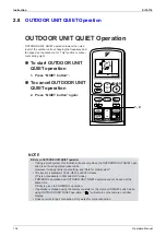
Page 145: ...tion will work only when the OUTDOOR UNIT QUIET oper ation is set on all operated indoor units However if using priority room setting see Note for multi system This function is available in COOL HEAT and AUTO modes This is not available in FAN and DRY mode POWERFUL operation and OUTDOOR UNIT QUIET operation cannot be used at the same time Priority is given to POWERFUL operation If operation is sto...

Page 146: ...ion stop button causes the settings to be canceled and the disappears from the LCD ECONO operation is a function which enables efficient operation by limiting the power consumption of the outdoor unit operating frequency ECONO operation functions in COOL and DRY modes The fan strength does not change in ECONO operation POWERFUL operation and ECONO operation cannot be used at the same time Priority...

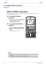
Page 147: ...r two seconds is displayed on the LCD To cancel MOLD PROOF operation 2 Press and hold the MOLD PROOF button for two seconds one more time disappears from the LCD NOTE MOLD PROOF operation will operate for approximately one hour after dry or cooling mode is turned off This function is not designed to remove existing dust or mold MOLD PROOF operation is not available when the unit is turned off usin...

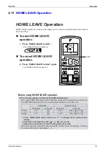
Page 148: ...VE operation for the first time please set the temperature and air flow rate for HOME LEAVE operation Record your preferred temperature and air flow rate 1 Press HOME LEAVE button Make sure is displayed in the remote control display 2 Adjust the set temperature with or as you like 3 Adjust the air flow rate with FAN setting button as you like Home leave operation will run with these settings the n...

Page 149: ...e welcomed by a comfortably air conditioned room Push the HOME LEAVE Opera tion button again and the air con ditioner will adjust capacity to the set temperature for normal opera tion Set the unit to HOME LEAVE Oper ation before leaving the living room when going to bed The unit will maintain the tem perature in the room at a com fortable level while you sleep When you enter the living room in the...

Page 150: ... EYE operation 1 Press SENSOR button is displayed on the LCD To cancel the INTELLIGENT EYE operation 2 Press SENSOR button again disappears from the LCD EX TEMP ON OFF POWERFUL MODE FAN SWING QUIET SENSOR ECONO MOLDPROOF TIMER ON CANCEL OFF 1 2 When somebody in the room Normal operation When nobody in the room 20 min after start energy saving operation Somebody back in the room Back to normal oper...

Page 151: ...ion the speed of pass ersby temperature range etc The sensor also mistakenly detects pets sunlight fluttering curtains and light reflected off of mirrors as passersby INTELLIGENT EYE operation will not go on during powerful operation Night set mode will not go on during you use INTELLIGENT EYE operation Do not place large objects near the sensor Also keep s heating units or humidifiers outside the...

Page 152: ...To start INTELLIGENT EYE operation 1 Press SENSOR button is displayed on the LCD To cancel the INTELLIGENT EYE operation 2 Press SENSOR button again disappears from the LCD EX TIMER ON CANCEL OFF 1 2 When somebody in the room Normal operation When nobody in the room 20 min after start energy saving operation Somebody back in the room Back to normal operation ...

Page 153: ...it location the speed of passersby temperature range etc The sensor also mistakenly detects pets sunlight fluttering curtains and light reflected off of mirrors as passersby INTELLIGENT EYE operation will not go on during powerful operation Night set mode will not go on during you use INTELLIGENT EYE operation Do not place large objects near the sensor Also keep heating units or humidifiers outsid...

Page 154: ...t To start INTELLIGENT EYE operation 1 Press SENSOR button To cancel the INTELLIGENT EYE operation 2 Press SENSOR button again EX C TEMP ON OFF POWERFUL HOME LEAVE MODE FAN SWING QUIET SENSOR 1 2 When somebody in the room Normal operation When nobody in the room 20 min after start energy saving operation Somebody back in the room Back to normal operation ...

Page 155: ...ect moving objects further than 5m away Check the application range Sensor detection sensitivity changes according to indoor unit location the speed of pass ersby temperature range etc The sensor also mistakenly detects pets sunlight fluttering curtains and light reflected off of mirrors as passersby INTELLIGENT EYE operation will not go on during powerful operation Night set mode will not go on d...

Page 156: ...on changes the setting rapidly 3 Press OFF TIMER button again The TIMER lamp lights up To cancel the OFF TIMER operation 4 Press CANCEL button The TIMER lamp goes off Notes When TIMER is set the present time is not displayed Once you set ON OFF TIMER the time setting is kept in the memory The memory is canceled when remote controller batteries are replaced When operating the unit via the ON OFF Ti...

Page 157: ...the setting rapidly 3 Press ON TIMER button again The TIMER lamp lights up To cancel ON TIMER operation 4 Press CANCEL button The TIMER lamp goes off To combine ON TIMER and OFF TIMER A sample setting for combining the two timers is shown below ATTENTION In the following cases set the timer again After a breaker has turned OFF After a power failure After replacing batteries in the remote controlle...

Page 158: ...es initial programming during installation Please consult your retailer or dealer for assistance NIGHT QUIET Mode reduces the operation noise of the outdoor unit during the night time hours to prevent annoyance to neighbors The NIGHT QUIET Mode is activated when the temperature drops 5 C or more below the highest temperature recorded that day Therefore when the temperature difference is less than ...

Page 159: ... UNIT QUIET operation Example Room A is the Priority Room in the examples Just by setting the unit in Room A to QUIET operation the air conditioner starts OUTDOOR UNIT QUIET operation You don t have to set all the operated indoor units to QUIET operation When the simultaneous operational capacity is exceeded If the simultaneous operational capacity is exceeded for outdoor unit capacity the indoor ...

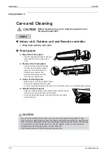
Page 160: ...he front panel Set the 2 keys of the front panel into the slots and push them in all the way Close the front panel slowly and push the panel at the 3 points 1 on each sides and 1 in the middle CAUTION Units Don ouch the metal parts of the indoor unit If you touch those parts this may cause an injury When removing or attaching the front panel use a robust and stable stool and watch your steps caref...

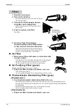
Page 161: ...ral detergent thinned with lukewarm water then dry them up in the shade It is recommended to clean the air filters every two weeks Air Purifying Filter green Replace approximately once every 3 months 1 Detach the filter element and attach a new one Insert with the green side up It is recommended to replace the air purifying filter every three months Photocatalytic Deodorizing Filter gray Maintenan...

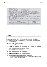
Page 162: ...ing filter Remove the dust periodi cally with a vacuum cleaner However it is recommended to replace the filter in the following cases 1 The paper material is torn or broken during cleaning 2 The filter has become extremely dirty after long use To order air purifying filter or photocatalytic deodorizing filter contact to the service shop where you bought the air conditioner Dispose of old air filte...

Page 163: ... dry it with cloth dry it up in the shade after washing 4 Attach the front panel Align the rotation dowels on the left and right of the front panel with the slots then push them all the way in Close the front panel slowly Press the panel at both sides and the center CAUTION Units Don t touch the metal parts of the indoor unit If you touch those parts this may cause an injury When removing or attac...

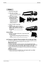
Page 164: ...t does not come off easily wash them with neutral detergent thinned with lukewarm water then dry them up in the shade It is recommended to clean the air filters every two weeks Titanium Apatite Photocatalytic Air purifying Filter The Titanium Apatite Photocatalytic Air Purifying Filter can be renewed by washing it with water once every 6 months We recommend replacing it once every 3 years Maintena...

Page 165: ...nnot deodorize the air 2 cannot clean the air 3 results in poor heating or cooling 4 may cause odour To order Titanium Apatite Photocatalytic Air Purifying Filter contact to the service shop there you bought the air conditioner Dispose of old filters as non flammable waste Check that the base stand and other fittings of the outdoor unit are not decayed or corroded Check that nothing blocks the air...

Page 166: ...et the 3 keys of the front grille into the slots and push them in all the way Close the front grille slowly and push the grille at the 3 points 1 on each sides and 1 in the middle Check to see if the rotating axis in the upper center section is moving CAUTION Units Don t touch the metal parts of the indoor unit If you touch those parts this may cause an injury When removing or attaching the front ...

Page 167: ... with neutral detergent thinned with lukewarm water then dry them up in the shade It is recommended to clean the air filters every two weeks Air Purifying Filter green Replace approximately once every 3 months 1 Detach the filter element and attach a new one Insert with the green side up It is recommended to replace the air purifying filter every three months Photocatalytic Deodorizing Filter gray...

Page 168: ...leaking from the indoor unit Stop operation and consult the ser vice shop if this is the case Operation with dirty filters 1 cannot deodorize the air 2 cannot clean the air 3 results in poor heating or cooling 4 may cause odour The air purifying filter and Photocatalytic deodorizing filter cannot be reused even if washed In principle there is no need to replace the photocatalytic deodorizing filte...

Page 169: ...nd start operation 2 After operation stops turn off the breaker for the room air conditioner 3 Clean the air filters and set them again 4 Take out batteries from the remote controller When a multi outdoor unit is connected make sure the heating operation is not used at the other room before you use the fan operation NOTE Check that the base stand and other fittings of the outdoor unit are not deca...

Page 170: ...es from the remote controller When a multi outdoor unit is connected make sure the heating operation is not used at the other room before you use the fan operation Do not operate the air conditioner without filters this to avoid dust accumulation inside the unit Do not remove the air filter except when cleaning Unnecessary handling may damage the filter Do not use gasoline benzene thinner polishin...

Page 171: ...icated by Operation without air filters may result in troubles as dust will accumulate inside the indoor unit CAUTION Units Don t touch the metal parts of the indoor unit If you touch those parts this may cause an injury When opening and closing the front grille use a robust and stable stool and watch your steps carefully When opening and closing the front grille support the grille securely with h...

Page 172: ...arm water then dry them up in the shade It is recommended to clean the air filters every two weeks Air Purifying Filter green Replace approximately once every 3 months 1 Detach the filter element and attach a new one Insert with the green side up It is recommended to replace the air purifying filter every three months Photocatalytic Deodorizing Filter gray Maintenance 1 Dry the photocatalytic deod...

Page 173: ...e leaking from the indoor unit Stop operation and consult the ser vice shop if this is the case Operation with dirty filters 1 cannot deodorize the air 2 cannot clean the air 3 results in poor heating or cooling 4 may cause odour The air purifying filter and Photocatalytic deodorizing filter cannot be reused even if washed In principle there is no need to replace the photocatalytic deodorizing fil...

Page 174: ...r filter Remove the Air purifying filter with photocatalytic deodorizing function then clean the air filter Clean the filter with water or vacuum cleaner To clean up heavy dirt wash the filter with a mild neutral detergent dissolved in luke warm water and dry in the shade Attach the Air purifying filter with photocatalytic deodorizing function the air filter and the front grille Insert the tabs at...

Page 175: ...ocatalytic deodorizing function In case of maintenance or changing Hold the knobs of the filter frame and remove tabs from 4 positions Air filter A filter frame In case of maintenance a filter frame Remove dust with a vacuum cleaner and wash lightly with water If it is very dirty soak it for 10 to 15 minutes in water mixed with a neutral cleaning agent Do not remove filter from frame when washing ...

Page 176: ...cted or broken Check that the drain comes smoothly out of the drain hose during COOL or DRY operation If no drain water is seen water may be leaking from the indoor unit Stop operation and consult the ser vice shop if this is the case NOTE Operation with dirty filters 1 3 results in poor cooling cannot deodorize the air 2 cannot clean the air 4 may cause odour To order air purifying filter with ph...

Page 177: ... steam when the air conditioner is in defrost operation In COOL or DRY mode Moisture in the air condenses into water on the cool surface of outdoor unit piping and drips Mists come out of the indoor unit This happens when the air in the room is cooled into mist by the cold air flow during cooling operation The indoor unit gives out odour This happens when smells of the room furniture or cigarettes...

Page 178: ...ck the air inlet or the outlet of the indoor and the outdoor units Clean the air filters or take all obstacles away and turn the breaker OFF Then turn it ON again and try operating the air conditioner with the remote controller If the lamp still flashes call the service shop where you bought the air conditioner Are operation modes all the same for indoor units connected to outdoor units in the mul...

Page 179: ...nce It is recommended to have periodical maintenance by a specialist aside from regular cleaning by the user For specialist maintenance contact the service shop where you bought the air conditioner The maintenance cost must be born by the user Call the service shop immediately After a power failure The air conditioner automatically resumes operation in about 3 minutes You should just wait for a wh...

Page 180: ...door Units 186 5 8 Unspecified Voltage between Indoor and Outdoor Units 188 5 9 Freeze up Protection Control 189 5 10 OL Activation Compressor Overload 191 5 11 Compressor Lock 192 5 12 DC Fan Lock 193 5 13 Input Over Current Detection 194 5 14 Four Way Valve Abnormality 196 5 15 Discharge Pipe Temperature Control 198 5 16 High Pressure Control in Cooling 199 5 17 Position Sensor Abnormality 201 5...

Page 181: ...ons disabling equipment operation 2 When a signal transmission error occurs between the indoor and outdoor units In either case conduct the diagnostic procedure described in the following pages Location of Operation Lamp In case of In case of FTKD 25 35 D Series FTK X E 25 35 B In case of FTK X D 50 60 71 F Series In case of CDK X D 25 35 50 60 C Series CDK X D 25 35 E Series R4298 ON OFF OPERATIO...

Page 182: ... above steps there is no malfunction Operation stops and operation lamp blinks only for indoor unit which the different operation mode is set later The first set operation mode has priority Troubleshooting with the LED Indication Outdoor Unit There are green and red LEDs on the PCB The flashing green LED indicates normal equipment condition and the OFF condition of the red LED indicates normal equ...

Page 183: ...model Diagnosis with indoor unit LED indication 177 Diagnosis with outdoor unit LED indication 178 Some indoor units do not operate Check the type of the indoor units Check to make sure that the indoor unit type is compatible with the outdoor unit Diagnosis with indoor unit LED indication 177 Diagnosis with outdoor unit LED indication 178 Equipment operates but does not cool or does not heat only ...

Page 184: ...s indicate non corresponding codes 2 To cancel the code display hold the timer cancel button down for 5 seconds The code display also cancels itself if the button is not pressed for 1 minute No Code No Code No Code 1 00 12 C7 23 H0 2 U4 13 H8 24 E1 3 F3 14 J3 25 P4 4 E6 15 A3 26 L3 5 L5 16 A1 27 L4 6 A6 17 C4 28 H6 7 E5 18 C5 29 H7 8 F6 19 H9 30 U2 9 C9 20 J6 31 UH 10 U0 21 UA 32 EA 11 E7 22 A5 33...

Page 185: ...k 2 Press the TEMP button Press TEMP or TEMP and change the digit until you hear the sound of beep or pi pi 3 Diagnose by the sound pi The number of tens does not accord with the error code pi pi The number of tens accords with the error code beep The both numbers of tens and units accord with the error code See 7 4 Enter the diagnosis mode again Press the MODE button The digit of the number of un...

Page 186: ...th numbers of tens and units do not accord with the error code pi pi The number of tens accords with the error code beep The both numbers of tens and units accord with the error code 7 Determine the error code The digits indicated when you hear the beep sound are error code Error codes and description Refer to page 176 8 Exit from the diagnosis mode Press the MODE button R4277 R4278 ...

Page 187: ... thermistor abnormality C9 Room temperature thermistor abnormality Outdoor Unit A5 Freeze up protection control E5 OL activation compressor overloaded E6 Compressor lock E7 DC fan lock E8 Input over current detection EA Four way valve abnormality F3 Discharge pipe temperature control F6 High pressure control in cooling H6 Position sensor abnormality H8 CT or related abnormality H9 Outdoor air ther...

Page 188: ... normal condition Conduct a diagnosis of the outdoor unit A1 Indoor unit PCB abnormality 179 A5 Freeze up protection control or high pressure control heat pump model only 180 A6 Fan motor or related abnormality AC motor 182 DC motor 183 C4 Heat exchanger thermistor or related abnormality 185 C9 Room temperature thermistor abnormality 185 U4 Signal transmission error between indoor and outdoor unit...

Page 189: ...Outdoor unit in normal condition Conduct a diagnosis of the indoor unit UA Unspecified voltage between indoor and outdoor units 215 UH Anti icing function in other rooms 215 5 3 3 4 4 U0 Insufficient gas 212 5 4 3 3 4 U2 Low voltage detection 214 5 4 3 4 4 A5 Freeze up protection control 189 5 4 3 4 3 E5 OL activation compressor overload 191 5 3 4 4 3 E6 Compressor lock 192 5 4 4 4 4 E7 DC fan loc...

Page 190: ... Faulty indoor unit PCB Faulty connector connection Troubleshooting Note Connector Nos vary depending on models Control connector Connector connection check note YES Is it normal NO Correct connections Replace PCBs R1400 Caution Be sure to turn off power switch before connect or disconnect connector or parts damage may be occurred Model Type Connector No Wall Mounted Type Terminal strip Control PC...

Page 191: ...n according to the temperature detected by the indoor unit heat exchanger thermistor Malfunction Decision Conditions High pressure control During heating operations the temperature detected by the indoor heat exchanger thermistor is above 65 C Freeze up protection When the indoor unit heat exchanger temperature is below 0 C during cooling operation Supposed Causes Operation halt due to clogged air...

Page 192: ...umulation on the indoor unit heat exchanger YES YES Is there any short circuit Is it very dirty Is it very dirty Does it conform to the thermistor characteristic chart NO Provide sufficient air passage Clean the air filter Clean the heat exchanger Replace the indoor unit PCB Replace the thermistor replace the indoor unit PCB Caution Be sure to turn off power switch before connect or disconnect con...

Page 193: ... of the fan motor Detection error due to faulty control PCB Troubleshooting Check No 16 Refer to P 225 Rotate the fan by hand Check No 16 Check Hall IC Operate the fan Does it rotate NO Does it rotate smoothly Is there an output Is it at the rated voltage Is there conductivity NO Check the capacitor s conductivity Check the fan motor voltage immediately after re start Is it at the rated voltage Ch...

Page 194: ...onditions When the detected rotation speed does not reach the demanded rotation speed of the target tap and is less than 50 of the maximum fan motor rotation speed Supposed Causes Operation halt due to short circuit inside the fan motor winding Operation halt due to breaking of wire inside the fan motor Operation halt due to breaking of the fan motor lead wires Operation halt due to faulty capacit...

Page 195: ...put of fan motor connector Is motor power voltage DC 200V generated Is motor control power voltage DC 15V generated Turn off power supply and disconnect fan motor connector then turn power ON again Does it rotate Stop fan motor Is rotation number command pulse generated Is rotation number command pulse generated Check No 01 Check output of fan motor connector Check No 01 Check output of fan motor ...

Page 196: ...han 120 ohms or below about 50 C more than 1 860 kohms Note The values vary slightly in some models Supposed Causes Faulty connector connection Faulty thermistor Faulty PCB Troubleshooting Check No 06 Refer to P 219 C4 Indoor heat exchanger thermistor C9 Room temperature thermistor Check the connector connection YES Correct the connection Replace the thermistor Replace the indoor unit PCB Replace ...

Page 197: ...When the data sent from the outdoor unit cannot be received normally or when the content of the data is abnormal Supposed Causes Faulty outdoor unit PCB Faulty indoor unit PCB Indoor unit outdoor unit signal transmission error due to wiring error Indoor unit outdoor unit signal transmission error due to disturbed power supply waveform Indoor unit outdoor unit signal transmission error due to break...

Page 198: ... PCB Locate the cause of the disturbance of the power supply waveform and correct it Is there any wiring error NO R6471 Is LED A flashing Is the voltage 0 V NO Check No 10 Check power supply waveform Check the voltage of the indoor unit outdoor unit connection wires between No 1 and No 2 and between No 2 and No 3 YES YES NO Is there any disturbance NO Caution Be sure to turn off power switch befor...

Page 199: ... Wrong models interconnected Wrong indoor unit PCB mounted Indoor unit PCB defective Wrong outdoor unit PCB mounted or defective Troubleshooting Check the indoor and outdoor unit model numbers Match the compatible models Change for the specified PCB 1 or 2 Replace the indoor unit PCB or the outdoor unit PCB R6954 Caution Be sure to turn off power switch before connect or disconnect connector or pa...

Page 200: ... the cooling mode the following conditions A and B are kept together for 5 minutes A Indoor unit heat exchanger temperature 1 C B Indoor unit heat exchanger temperature Room temperature 10 C If the freeze up protection control is activated 4 times continuously the system will be shut down The 4 time counter will reset itself if any of the following errors does not occur for 60 minutes OL radiation...

Page 201: ...hanger thermistor Do the vacuum drying Replace the indoor unit PCB and then start the wiring error check mode R4715 Caution Be sure to turn off power switch before connect or disconnect connector or parts damage may be occurred Wiring or piping out of spec YES NO NO YES NO YES NO YES YES NO Error again Motor functioning Thermistor as specified in its characteristic chart Thermistor as specified in...

Page 202: ...valve defective Troubleshooting Check No 04 Refer to P 217 Check No 05 Refer to P 218 Check No 06 Refer to P 219 Check No 11 Refer to P 222 Insert the thermistor in position Replace the discharge pipe thermistor Replace the valve itself or the coil Replace the four way valve coil or the valve itself Replace the outdoor unit PCB Refer to the refrigerant line check procedure R4697 Caution Be sure to...

Page 203: ...hut down if the error occurs 16 times Clearing condition Continuous run for about 5 minutes normal Supposed Causes Compressor locked Troubleshooting Turn off the power Disconnect the harnesses U V and W Inverter checker Part No 1225477 Correct the power supply or replace the SPM Replace the outdoor unit PCB Replace the compressor Check the electronic expansion valve Replace it as required Replace ...

Page 204: ...ition Continuous run for about 5 minutes normal Supposed Causes Fan motor breakdown Harness or connector disconnected between fan motor and PCB or in poor contact Foreign matters stuck in the fan Troubleshooting Check No 15 Refer to P 224 Turn off the power and reconnect the connector Remove Replace the outdoor unit fan motor Replace the outdoor unit PCB R2843 Caution Be sure to turn off power swi...

Page 205: ...ns The following condition continues for 2 5 seconds Input current 16 5A typical value The compressor halts if the error occurs and restarts automatically after 3 minutes stand by Supposed Causes Over current due to compressor failure Over current due to defective power transistor Over current due to defective inverter main circuit electrolytic capacitor Over current due to defective outdoor unit ...

Page 206: ...above its stop level NO YES Normal NO YES Any LED off YES NO Check with the inverter checker Turn off the power and reconnect the harnesses Turn on the power again and get restarted Turn off the power and disconnect the harnesses U V and W Get restarted and measure the input current Check No 08 Check the discharge pressure Check No 07 Check the installation condition Check No 14 Check the main cir...

Page 207: ...thin their normal ranges in the operating mode Malfunction Decision Conditions Either of the following conditions occurs 6 minutes after the compressor has started Cooling dry operation Outdoor unit heat exchanger temperature Liquid pipe temperature 5 C Heating operation Liquid pipe temperature Outdoor unit heat exchanger temperature 0 C Supposed Causes Connector in poor contact Thermistor defecti...

Page 208: ...urn off power switch before connect or disconnect connector or parts damage may be occurred Four way valve coil disconnected loose YES YES NO Functioning NO Check No 11 Check the refrigerant line Malfunctioning z Water mixed z Shut off valve defective Harness out of connector NO YES Disconnect the harness from the connector Resistance between harnesses about 1500 ohms Malfunctioning Functioning Ch...

Page 209: ...he system will be shut down The error counter will reset itself if this or any other error does not occur during the following 60 minute compressor running time total time Supposed Causes Refrigerant shortage Four way valve malfunctioning Discharge pipe thermistor defective heat exchanger or outdoor temperature thermistor defective Outdoor unit PCB defective Water mixed in the local piping Electro...

Page 210: ...erature being sensed by the heat exchanger thermistor exceeds the limit Malfunction Decision Conditions Activated when the temperature being sensed by the heat exchanger thermistor rises above 65 C The error is cleared when the temperature drops below 50 C Supposed Causes The installation space is not large enough Faulty outdoor unit fan Faulty electronic expansion valve Faulty outdoor unit heat e...

Page 211: ... the connector or fan motor lead wires Replace the heat exchanger thermistor Replace PCB Replace the electronic expansion valve or coil Replace the PCB Change the air outlet grille position Change the installation location Clean the heat exchanger Check the installation space Check No 09 Outdoor fan check Judgment Check No 06 Heat exchanger thermistor check Judgment Check No 07 Installation condit...

Page 212: ...ssor relay cable disconnected Compressor itself defective Outdoor unit PCB defective Stop valve closed Input voltage out of specification Troubleshooting Check No 13 Refer to P 223 Replace the outdoor unit PCB outdoor unit fan Replace the outdoor unit PCB Reconnect as specified Inverter checker Part No 1225477 Correct the power supply or replace the outdoor unit PCB Replace the compressor R5145 Ca...

Page 213: ...rrent Malfunction Decision Conditions The compressor running frequency is below 55 Hz and the CT input is below 0 1 V The input current is also below 1 25 A If this error repeats 4 times the system will be shut down The error counter will reset itself if this or any other error does not occur during the following 60 minute compressor running time total time Supposed Causes Power transistor defecti...

Page 214: ...itch before connect or disconnect connector or parts damage may be occurred Running current as shown at right with relay cable 1 or 2 YES Current guideline 2 sec Time Rising with increasing frequency Capacitor charged when the indoor unit or outdoor unit main relay turns on NO NO DC320 30V YES Voltage within the allowable range Supply voltage 15 YES NO Any LED off Compressor running YES NO YES NO ...

Page 215: ...stor Malfunction Decision Conditions When the thermistor input is above 4 96 V or below 0 04 V with the power on the J3 error is judged if the discharge pipe thermistor temperature is smaller than the condenser thermistor temperature or the system will be shut down if all the units are judged with the J8 error Supposed Causes Connector in poor contact Thermistor defective Outdoor unit PCB defectiv...

Page 216: ...e following thermistor z Indoor unit heat exchanger thermistor Replace the outdoor unit PC board Replace the indoor unit PC board R4718 Caution Be sure to turn off power switch before connect or disconnect connector or parts damage may be occurred Error displayed again on remote controller NO YES YES YES NO Indoor unit heat exchanger thermistor functioning NO Connector or thermistor disconnected N...

Page 217: ...ng the radiation fin thermistor with the compressor off Malfunction Decision Conditions With the compressor off the radiation fin temperature is above C The error is cleared when the temperature drops below C Supposed Causes Fin temperature rise due to defective outdoor unit fan Fin temperature rise due to short circuit Fin thermistor defective Connector in poor contact Outdoor unit PCB defective ...

Page 218: ...ution Be sure to turn off power switch before connect or disconnect connector or parts damage may be occurred Error again or outdoor unit fan activated YES z Fin thermistor NO Slightly dirty Check No 09 Check the outdoor unit fan or related Malfunctioning Radiation fin dirty Too dirty Functioning Thermistor as specified in its characteristic chart Above 80 C NO YES NO YES Check the radiation fin t...

Page 219: ...e error is cleared when the temperature drops below C If a radiation fin temperature rise takes place 255 times successively the system will be shut down The error counter will reset itself if this or any other error does not occur during the following 60 minute compressor running time total time Supposed Causes Fin temperature rise due to defective outdoor unit fan Fin temperature rise due to sho...

Page 220: ...its characteristic chart Above 90 C NO YES NO YES z Fin thermistor Check the radiation fin temperature Check No 07 Check the installation condition Turn off the power and turn it on again to get the system started Check No 06 Check the thermistor resistance value Check if the silicon grease applied properly on the radiation fin If not apply it Note 1 Silicon grease Part No 1172698 Replace the fin ...

Page 221: ...s while the compressor is running An output over current input is fed from the output over current detection circuit to the microcomputer The system will be shut down if the error occurs 16 times Clearing condition Continuous run for about 5 minutes normal Supposed Causes Over current due to defective power transistor Over current due to wrong internal wiring Over current due to abnormal supply vo...

Page 222: ...ected for part replacement for example and the system is interrupted by an output over current take the following procedure Error again NO YES NO YES Voltage as rated YES NO Short circuit or breakage between compressor s coil phases NO YES Normal YES NO Any LED off Turn off the power and turn it on again to get the system started See if the same error occurs Turn off the power and disconnect the h...

Page 223: ...rrent input voltage 1756 256 output frequency 50 W Output frequency 55 Hz Gas shortage detection II The following conditions continue for 80 seconds Target opening of the electronic expansion valve 450 pulse Cooling discharge temperature 255 256 target discharge temperature 20 C Heating discharge temperature 255 256 target discharge temperature 40 C If a gas shortage error takes place 4 times stra...

Page 224: ...exchanger thermistor 1 Replace the PCB 2 Replace the compressor Procedure complete R4719 Caution Be sure to turn off power switch before connect or disconnect connector or parts damage may be occurred Any thermistor disconnected YES Malfunctioning Malfunctioning NO Functioning Stop valve closed NO YES Check the CT YES NO Gas shortage error again Functioning Check No 06 Check the thermistors YES NO...

Page 225: ...upposed Causes Supply voltage not as specified Over voltage detector or DC voltage detection circuit defective PAM control part s defective Short circuit inside the fan motor winding Troubleshooting Check the supply voltage Correct the power supply Replace the SPM or PM1 Replace the outdoor unit PCB Check for such factors for a long term Try to get restarted a couple of times R6567 Caution Be sure...

Page 226: ...tion halt due to unspecified internal and or external voltages Operation halt due to mismatching of indoor and outdoor units Supposed Causes Operation halt due to the anti icing function in other rooms Wrong connections at the indoor unit PCB wrongly connected Troubleshooting Check the model name The freeze protection function is activated in other rooms Refer to A5 Correct Reconnect R3066 Caution...

Page 227: ...eck connector connection 2 Check motor control voltage output pins 2 1 7 6 5 4 3 2 1 Motor power supply voltage Unused Unused P 0V reference potential Motor control voltage 15 VDC Rotation command voltage 1 5 VDC Rotation pulse input S1 or S301 8 7 6 5 4 3 2 1 Motor power supply voltage Unused Unused Unused P 0V reference potential Motor control voltage 15 VDC Rotation command voltage 1 to 5 VDC R...

Page 228: ...he no operation unit Flow noise of refrigerant in the no operation unit Operation halt due to icing protection Heating The unit does not heat Refrigerant flow rate vary by unit Discharge air temperatures are different by room Peak cut Reset power supply and conduct cooling operation unit by unit 2 Valve body catches at complete close position Symptom Cooling The only unit having problem does not c...

Page 229: ...nit PCB Replace the four way valve coil Replace the four way valve R5153 NO Four way valve coil Cooling dry No continuity Heating Continuity YES YES Four way valve coil resistance at 1500 ohms NO S80 voltage at DC 220 240 V with compressor on Fig 1 Disconnect the four way valve coil from the connector and check the continuity Fig 1 Voltage at S80 DC220 240V ON Compressor Time ...

Page 230: ...rs on the PCB and measure the resistance of each thermistor using tester The relationship between normal temperature and resistance is shown in the graph and the table below Thermistor R25 C 20kΩ B 3950 Temperature C 20 211 0 kΩ 15 150 10 116 5 5 88 0 67 2 5 51 9 10 40 15 31 8 20 25 25 20 30 16 35 13 40 10 6 45 8 7 50 7 2 ...

Page 231: ...ger Change the installation location or direction Check the outside air temperature temperature of air taken in by the outdoor unit The outside air temperature shall be 46 C or lower Check the allowable dimensions of the air suction and discharge area Is the air flow blocked by obstacles or winds blowing in the opposite direction R3048 Abnormal YES YES YES Does the discharged air from other outdoo...

Page 232: ...p valve Replace the pipe installed at the site Clean Replace the compressor R1443 YES YES YES NO NO NO NO At the heat exchanger and air filter dirty Is the stop valve open Is the connection pipe deformed YES High Check the outdoor unit fan system Reconnect R2857 Outdoor unit fan running YES Fan motor lead wire connector disconnected YES NO NO Outdoor unit fan system functioning Go to Check No 15 ...

Page 233: ...eform disturbance near the zero cross sections circled in Fig 2 6 1 9 Inverter Units Refrigerant System Check Check No 11 Fig 1 Fig 2 Refrigerant system check Check for gas leaks See the section on insufficient gas detection Conduct the check after operating the equipment for a sufficient length of time Correct the problem Conduct vacuum drying Replace the refrigerant Is the discharge thermister d...

Page 234: ...e the power transistor s supply voltage is below 50 V using the tester z For the UVW make measurements at the Faston terminal on the board or the relay connector Fan motor lead wire Solenoid valve coil lead wire Room A Solenoid valve coil lead wire Room B Solenoid valve coil lead wire Room C Solenoid valve lead wire Thermistor lead wire liquid pipe Thermistor lead wire gas pipe Thermistor lead wir...

Page 235: ...s being applied 1 Stop the operation first and then the power and disconnect the connector S70 2 Make sure there is about DC 320 V between pins 4 and 7 3 With the system and the power still off reconnect the connector S70 4 Make a turn of the fan motor with a hand and make sure the pulse 0 15 V appears twice at pins 1 and 4 If the fuse is blown out the outdoor unit fan may also be in trouble Check...

Page 236: ...nected check the following Output voltage of about 5 V between pins 1 and 3 Generation of 3 pulses between pins 2 and 3 when the fan motor is operating Failure of 1 Æ faulty PCB Æ Replace the PCB Failure of 2 Æ faulty Hall IC Æ Replace the fan motor Both 1 and 2 result Æ Replace the PCB The connector has 3 pins and there are two patterns of lead wire colors ...

Page 237: ...Check Si12 714 226 Service Diagnosis ...

Page 238: ...of PCB 282 2 5 Removal of Fan Motor 285 2 6 Removal of Electronic Expansion Valve and Thermistor 287 2 7 Removal of Sound Blanket and Reactor 288 2 8 Removal of Shunt 290 2 9 Removal of Solenoid Valve and Four Way Valve 291 2 10 Removal of Compressor 293 3 Outdoor Unit 58 68 75 Class 295 3 1 Removal of Outer Panels 295 3 2 Removal of Electrical Box 296 3 3 Removal of PCB 300 3 4 Removal of Fan Mot...

Page 239: ...Panels Procedure Warning Be sure to wait 10 minutes or more after turning off all power supplies before disassembling work Step Procedure Points 1 Removing the suction grille 1 Undo the 2 hooks at the bottom first The hooks are secured in the clearances of the heat exchanger fins Hooks Suction grille ...

Page 240: ...lass Removal Procedure 229 2 Next slide the grille downward to undo the 3 top hooks 3 Remove the suction grille 2 Removing the top panel 1 Remove 3 screws on the back and 1 screw on the left side panel Step Procedure Points Hooks ...

Page 241: ...100 Class Si12 714 230 Removal Procedure 2 Remove 4 screws on the front and 1 screw on the right side panel 3 Lift the top panel and remove it 3 Removing the right side panel 1 Remove 4 screws Step Procedure Points ...

Page 242: ...Si12 714 Outdoor Unit 100 Class Removal Procedure 231 2 Slide the panel downward to undo 2 hooks on the back side Step Procedure Points Hooks Hooks Hook Holes Hook Holes Hook Holes ...

Page 243: ...t panel 2 1 Remove the 2 screws 2 There is a hook at the top of the front panel 2 Slightly lift the front panel off position The hook is provided to keep the front panel 2 secured in place It covers the top projections of the front panel 1 from above Step Procedure Points Front Panel 1 Front Panel 2 Hook ...

Page 244: ...Si12 714 Outdoor Unit 100 Class Removal Procedure 233 3 Slide the panel downward to undo 2 hooks 4 Remove the front panel 2 Step Procedure Points ...

Page 245: ...oving the front panel 1 Remove the discharge grille and propeller fan first to remove the front panel 1 1 Remove the 4 screws on the discharge grille 2 Pull the bottom of the discharge grille toward yourself Step Procedure Points Front Panel 1 Discharge grille ...

Page 246: ...Si12 714 Outdoor Unit 100 Class Removal Procedure 235 3 Next slide the grille downward to undo the 2 hooks at the top 4 Remove the discharge grille Step Procedure Points Hooks ...

Page 247: ...Outdoor Unit 100 Class Si12 714 236 Removal Procedure 5 Remove the 2 fixing screws from the fan motor mount 6 Remove the propeller fan fixing nut Fan fixing nut M8 Step Procedure Points Fixing screw ...

Page 248: ...Outdoor Unit 100 Class Removal Procedure 237 7 Remove the 2 fixing screws on the partition plate 8 Remove the screw at bottom left of the front 9 Remove the screw at bottom of the left side Step Procedure Points ...

Page 249: ...0 Class Si12 714 238 Removal Procedure 10 Remove the screw at bottom of the back side 11 The front panel 1 is provided with a hook on its front Lift the front panel off position to remove it Step Procedure Points Hook ...

Page 250: ...00 Class Removal Procedure 239 12 Remove the front panel 1 The back is a little complicated in shape Be sure to detach carefully 6 Removing the rear panel 1 Remove the fixing screw on the partition plate Step Procedure Points ...

Page 251: ...Outdoor Unit 100 Class Si12 714 240 Removal Procedure 2 Slide the panel leftward to undo the hooks 3 Remove the partition plate 4 Remove the 6 screws Step Procedure Points Hook ...

Page 252: ...Si12 714 Outdoor Unit 100 Class Removal Procedure 241 5 Remove the wire fixing plate 6 Remove the screw of the earth Step Procedure Points ...

Page 253: ...lass Si12 714 242 Removal Procedure 7 Undo the holder of the thermistor The holder is secured in the clearances of the heat exchanger fins 8 Remove the 3 fixing screws on the partition plate Step Procedure Points Groove ...

Page 254: ...00 Class Removal Procedure 243 9 Remove the fixing screw from the bottom frame 10 Remove the fixing screw from the shut off valve mounting plate 11 Lift the panel upward to undo the 2 hooks and remove it Step Procedure Points ...

Page 255: ...Outdoor Unit 100 Class Si12 714 244 Removal Procedure 12 The bottom is sandwiched in the bottom frame Lift up to detach 13 Remove the rear panel Step Procedure Points Hooks ...

Page 256: ...re to wait 10 minutes or more after turning off all power supplies before disassembling work Step Procedure Points 1 Remove the fixing screw from the shut off valve mounting plate 2 Remove the fixing screw on the partition plate 3 Open the cover of the electrical box Undo the 4 hooks The hooks are marked with W ...

Page 257: ...onnect the fan motor connector S70 5 Disconnect the fan motor wire harness 6 Disconnect the 4 motorized valve connectors for Rooms A B C and D A Connector S20 white B Connector S21 red C Connector S22 blue D Connector S23 yellow Step Procedure Points S70 A B C D ...

Page 258: ...ve connector S80 Detach the clamp Just pull the push mount type out of position 8 Disconnect the liquid pipe thermistor connector S93 9 Disconnect the gas pipe thermistor connector S92 10 Disconnect the discharge pipe thermistor connector S90 Step Procedure Points S80 clamp S93 S92 S90 ...

Page 259: ...8 Removal Procedure 11 Disconnect the OL connector S40 12 The wire harness is hooked on the bottom of the electrical box Unhook it and remove the clamp 13 Disconnect the 2 reactor wire harnesses Step Procedure Points S40 clamp Reactors ...

Page 260: ...harness and the compressor wire harness together from the partition 15 Use long nose pliers or the like to pull out the clamps Detach the clamp Just pull the push mount type out of position 16 Disconnect the relay connector of the compressor Step Procedure Points clamps clamps ...

Page 261: ...Procedure 17 Cut off the clamps of the OL wire harness and compressor wire harness Cut off with nippers 18 First slide the box leftward do undo the hook on the right side of the box 19 Lift up the electrical box to remove it Step Procedure Points ...

Page 262: ...3 Removal of PCB Procedure Warning Be sure to wait 10 minutes or more after turning off all power supplies before disassembling work Step Procedure Points 1 Removing the Control PCB 1 Remove the screw 2 Undo the 2 hooks 3 Lift up your side of the control PCB ...

Page 263: ...ectors S51 S101 For display PCB z Connector S10 For relay PCB z Connectors H1 H2 For DB diode bridge power wire harnesses AC1 red and AC2 black 5 Remove the control PCB 2 Removing the inverter PCB Connector L1 L2 1 Disconnect the reactor wire harness connector 2 Disconnect the rectifier stack connector Black and red Step Procedure Points Reactor wire harness connector Rectifier stack connector ...

Page 264: ...Unit 100 Class Removal Procedure 253 3 Disconnect the connector of the compressor Blue yellow red and brown 4 Remove the 7 screws 5 Lift the inverter PCB upward to remove it Step Procedure Points Connector of compressor ...

Page 265: ...Outdoor Unit 100 Class Si12 714 254 Removal Procedure 3 Removing the SPM 1 Remove the 2 screws 2 Remove the 2 screws 3 Remove the screw rectifier stack 4 Remove the rectifier stack Step Procedure Points ...

Page 266: ...00 Class Removal Procedure 255 5 Remove the SPM 4 Removing the display PCB 1 Remove the filament tape 2 Remove the drip proof cover 3 Slightly lift the top hooks to detach Step Procedure Points Filament tape Drip proof cover ...

Page 267: ...256 Removal Procedure 4 Undo the bottom hook to remove the display PCB 5 Removing the servicing cover off the terminal block assembly 1 2 Remove the screw Lift the hook to detach 3 Open the cover toward yourself Step Procedure Points ...

Page 268: ...turning off all power supplies before disassembling work Step Procedure Points 1 2 Remove the 2 screws at the bottom first Next remove the 2 top screws Be sure to remove the bottom screws first If the top screws are removed first the fan motor the center of gravity of which is toward the front may tilt down or fall getting you injured 2 1 ...

Page 269: ...Outdoor Unit 100 Class Si12 714 258 Removal Procedure 3 Remove the fan motor When reassembling be sure to place the wire harness lower Step Procedure Points Harness ...

Page 270: ...l of Coils Thermistors Procedure Warning Be sure to wait 10 minutes or more after turning off all power supplies before disassembling work Step Procedure Points 1 Removing the motorized valve coil 1 Pull the motorized valve coil out of position Motorized valve coil ...

Page 271: ...Outdoor Unit 100 Class Si12 714 260 Removal Procedure 2 Remove the clamp from the gas pipe thermistor and pull out the thermistor Step Procedure Points Gas pipe thermistor clamps ...

Page 272: ...t 100 Class Removal Procedure 261 3 Peel the putty from the liquid pipe thermistor and pull out the thermistor 2 Removal of Thermistors 1 Pull out the heat exchanger thermistor Step Procedure Points Liquid pipe thermistor ...

Page 273: ...Class Si12 714 262 Removal Procedure 2 Remove the spring from the heat exchanger thermistor Be careful not to lose the spring 3 Slightly open the sound blanket 4 Remove the insulation sleeve Step Procedure Points Spring ...

Page 274: ...14 Outdoor Unit 100 Class Removal Procedure 263 5 Remove the discharge pipe thermistor 6 Remove the fixture 3 Removing the Four way valve coil and motorized valve coil 1 Remove the screw Step Procedure Points ...

Page 275: ...Outdoor Unit 100 Class Si12 714 264 Removal Procedure 2 Remove the Four way valve coil 3 Remove the screw 4 Remove the motorized valve coil Step Procedure Points ...

Page 276: ...e 265 1 6 Removal of Reactor Procedure Warning Be sure to wait 10 minutes or more after turning off all power supplies before disassembling work Step Procedure Points 1 Remove the screw 2 Lift the reactor upward to undo the hooks 3 Remove the reactor ...

Page 277: ...ing Be sure to wait 10 minutes or more after turning off all power supplies before disassembling work Step Procedure Points 1 Disconnect the compressor wire harness from the partition plate Fixed at 2 locations 2 Undo the 2 Velcro tapes off the sound blanket and open the sound blanket outer sleeve ...

Page 278: ...t is fragile Carefully pass the discharge pipe through it 4 Remove the sound blanket outer sleeve The sound blanket is fragile Be careful of the notches of the compressor mount 3 locations 5 Remove the screw from the partition plate and open the plate slightly to the left for easy work Step Procedure Points ...

Page 279: ...he sound blanket is fragile Carefully pass the discharge pipe through it 7 Open the sound blanket inner sleeve and remove part of the muffler The sound blanket is fragile Be careful of the notches of the compressor mount 3 locations 8 Remove the sound blanket outer sleeve Step Procedure Points ...

Page 280: ... Compressor Procedure Warning Be sure to wait 10 minutes or more after turning off all power supplies before disassembling work Step Procedure Points 1 Remove the terminal cover 2 Pull out the 4 leads using long nose pliers U red V yellow W blue N brown 3 Remove the OL ...

Page 281: ...Outdoor Unit 100 Class Si12 714 270 Removal Procedure 4 Remove the screw Step Procedure Points ...

Page 282: ...90 Class 2 1 Removal of Outer Panels Procedure Warning Be sure to wait 10 minutes or more after turning off all power supplies before disassembling work Step Procedure Points 1 External appearance Remove the piping in the backward direction 2 Remove 11 screws of the top panel ...

Page 283: ...re 3 Unscrew 3 screws of the right panel slide it downwards and release the tabs to remove 4 The figure shows the view of piping connections 5 Unscrew 1 screw of the front right panel slide it downwards and release the tabs to remove Step Procedure Points ...

Page 284: ...80 90 Class Removal Procedure 273 6 Unscrew 3 screws of the front panel to remove 7 Remove 4 screws of the discharge outlet grill 8 Slide the discharge outlet grill upwards and release 6 tabs to remove Step Procedure Points ...

Page 285: ...fter turning off all power supplies before disassembling work Step Procedure Points Remove the discharge outlet grill 1 To take off propeller fan remove the washer fitted nut M8 2 Remove the propeller fan For reassembling align mark of propeller fan with D cut section of motor shaft Mount the propeller fan while positioning mark to the top ...

Page 286: ...such as top and front panels Match the colors of the tie wires to A B C and D ports as follows 1 Black Power 2 White Power 3 Red Transmission Wires are fixed to the terminal board with screws 1 The figure shows the right side view 1 Remove the tie wire 1 Loosen the terminal board screws and remove the wires at A and B ports 2 Open the terminal board cover and remove the wires at C and D ports When...

Page 287: ...earth wire 4 Remove 1 screw of the terminal board 5 Release the tab on the top right of the terminal board 6 Pull out the terminal board and open it Glass tube fuse and varistor cannot be replaced individually because lead free soldering is provided Step Procedure Points ...

Page 288: ...ion valve lead wires When reconnecting make sure to match the wire to the correct connector 2 Remove the four way valve connector S80 3 Remove the connector S93 for liquid pipe thermistor Step Procedure Points Connector Electronic expansion valve No Harness length S20 White EVA 630 S21 Red EVB 730 S22 Blue EVC 825 S23 Yellow EVD 940 ...

Page 289: ...he connector S92 for gas pipe thermistor 5 Remove the connector S90 for thermistor Outdoor air thermistor Blue Discharge pipe thermistor Black Heat exchanger thermistor Gray 6 Remove the overload relay connector S40 7 Remove the reactor lead wire Step Procedure Points ...

Page 290: ... Unit 80 90 Class Removal Procedure 279 8 Remove the relay connector for compressor 9 Remove the electrical box cover 10 Disconnect the fan motor connector 11 Remove the discharge pipe thermistor Step Procedure Points ...

Page 291: ...hermistor so that its end comes up to the end of the presser spring Be careful not to lose the presser spring for the discharge pipe thermistor 3 Removing the electrical box 1 Remove 2 screws of the electrical box 2 Turn the electrical box up side down halfway and disconnect the thermistor lead wire from the hook Step Procedure Points ...

Page 292: ...714 Outdoor Unit 80 90 Class Removal Procedure 281 3 Remove the outdoor air thermistor lead wire from the groove 4 Remove each wire harness and dismount the electrical box by lifting it Step Procedure Points ...

Page 293: ... 10 minutes or more after turning off all power supplies before disassembling work Step Procedure Points 1 Removing the controller PCB 1 Release the tab of the electrical box and open the terminal board 2 Disconnect each connector of the terminal board 3 Unscrew 1 screw and release two tabs to remove the PCB ...

Page 294: ...Si12 714 Outdoor Unit 80 90 Class Removal Procedure 283 4 Lift the PCB at the terminal board side 5 Disconnect each wire harness connector linked to the inverter PCB Step Procedure Points ...

Page 295: ...ic expansion valve coil D port S31 To CN14 Pin 9 S32 To CN11 Pin 5 S33 To S34 Pin 10 S40 Overload relay S71 To S72 Pin 8 S80 Four way valve coil S90 Thermistor Outdoor air heat exchanger and discharge pipe S92 Gas pipe thermistor S93 Liquid pipe thermistor 2 Removing the service monitor PCB 1 Remove the service monitor PCB by releasing its tab 3 Removing the inverter PCB 1 Remove the 9 screws of t...

Page 296: ...g off all power supplies before disassembling work Step Procedure Points Remove the outer panels 1 Remove the fan motor lead wire connector S70 2 Remove the propeller fans For reassembling align mark of propeller fan with D cut section of motor shaft Mount the fan motor so as to position Q mark on the top 3 Remove 2 screws of the fan motor mount ...

Page 297: ... Si12 714 286 Removal Procedure 4 Remove 4 screws of the fan motor When reassembling fix the lead wire to avoid contact with the propeller fan 5 Cut the wrapper fixing the lead wire 6 Remove the fan motor Step Procedure Points ...

Page 298: ...he thermistor so that its end comes up to the end of the presser spring Be careful not to lose the presser spring for the discharge pipe thermistor 2 Take off the putty and remove each thermistor S90 Outdoor air thermistor Blue Heat exchanger thermistor Gray Discharge pipe thermistor Black S92 Gas pipe thermistor Room A Black Room B Gray Room C Brown Room D Red S93 Liquid pipe thermistor Room A Bl...

Page 299: ...upplies before disassembling work Step Procedure Points 1 Release the clip fixing the compressor lead wire 2 Remove 2 screws of the partition board and move the board leftward The partition board is not removable as it is fixed with the fitting screw in the rear bottom 3 Remove the sound blanket outer Carefully remove the sound blanket which is easily torn in the piping section ...

Page 300: ...90 Class Removal Procedure 289 4 Remove the sound blanket top Carefully remove the sound blanket which is easily torn in the piping section 5 Remove the sound blanket inner 6 Remove 1 screw of the reactor Step Procedure Points ...

Page 301: ...sten the rubber packing with double faced adhesive tape when mounting 3 Remove the putty Caution Be careful not to get yourself burnt with the pipes and other parts that are heated by the gas welding rod Warning If refrigerant gas leaks during the job ventilate the room Bear in mind that if the refrigerant gas is exposed to open flames noxious gas may be generated Before taking this procedure make...

Page 302: ...noid valve 1 Remove 1 screw of the solenoid valve coil Before taking this procedure make sure there is no refrigerant gas left in the refrigerant pipes 2 Disconnect the 2 brazed points a and b in this order Warning If refrigerant gas leaks during the job ventilate the room Bear in mind that if the refrigerant gas is exposed to open flames noxious gas may be generated 2 Removing the four way valve ...

Page 303: ...the pipes be careful not to over tighten them with pliers The pipes may get deformed If the gas welding machine fails to remove the four way valve take the steps below 1 Disconnect the brazed pipe sections that are readily easy to separate and join together later 2 With a small copper tube cutter cut off the internal pipes to easily take out the four way valve Note Never use a hack saw The sawdust...

Page 304: ... off all power supplies before disassembling work Step Procedure Points 1 Remove the terminal cover Be careful to avoid burning the compressor terminals or the nameplate 2 Remove the overload relay 3 Disconnect the flag shape terminal As precaution keep the contents in memorandum 4 There is one nut fixing the compressor Remove the nut with a spanner ...

Page 305: ...s during the job ventilate the room Bear in mind that if the refrigerant gas is exposed to open flames noxious gas may be generated Caution Be careful not to get yourself burnt with the pipes and other parts that are heated by the gas welding rod When heating up the brazed parts make sure to carry out the N2 replacement 5 Remove the 2 sheets of putty 6 Disconnect the brazed part a at discharge sid...

Page 306: ...ls Procedure Warning Be sure to wait 10 minutes or more after turning off all power supplies before disassembling work Step Procedure Points 1 External appearance 2 Remove 4 screws of the top panel and 6 screws of the front panel 3 Remove 4 screws of the discharge outlet grill 4 Remove 2 screws of the piping cover ...

Page 307: ...ing work Step Procedure Points 1 Removing the tie wires Remove the piping in the backward direction 1 The figure shows the tie pipe connections 2 Remove the terminal board fitting screw Match the colours of the tie wires to A B C and D ports as follows 1 Black Power 2 White Power 3 Red Transmission Wires are fixed to the terminal board with screws Terminal board is made of integral moulded resin ...

Page 308: ...e correct connector 1 Disconnect 4 connectors of the electronic expansion valve lead wires 2 Remove the four way valve connector S80 3 Disconnect the thermistor connector and the overload relay connector S40 Overload relay S90 Thermistor Outdoor air heat exchanger discharge pipe S92 Gas pipe thermistor S93 Liquid pipe thermistor Step Procedure Points Connector Electronic expansion valve No Harness...

Page 309: ...al Procedure 4 Disconnect the compressor relay connector 5 Remove the reactor lead wire 3 Removing the wiring fixture 1 Remove 6 screws of the wiring fixture 4 Removing the electrical box 1 Remove 1 screw of the electrical box Step Procedure Points ...

Page 310: ...r Unit 58 68 75 Class Removal Procedure 299 2 Remove 1 screw of the electrical box 3 Remove the drip proof cover 4 Disconnect the fan motor lead wire 5 Lift up the electrical box and dismount it Step Procedure Points ...

Page 311: ...supplies before disassembling work Step Procedure Points 1 Removing the controller PCB 1 Remove 1 screw of the PCB and release 2 tabs 2 Release the tabs of the terminal board and open the terminal board 3 Disconnect each connector on the back of the terminal board 4 Disconnect the service monitor PCB connector Release the tab to remove the service monitor PCB ...

Page 312: ... 58 68 75 Class Removal Procedure 301 5 Lift up the control PCB 6 Disconnect each wire harness connector linked to the control PCB S31 Pin 9 To CN14 S32 Pin 5 To CN11 S33 Pin 10 To S34 S71 Pin 8 To S72 Step Procedure Points ...

Page 313: ...val Procedure 7 The figure shows the control PCB Glass tube fuse 3A 2 Removing the service monitor PCB 1 The figure shows the service monitor PCB 3 Removing the inverter PCB MID2 1 Remove the 7 screws of the inverter PCB MID2 Step Procedure Points ...

Page 314: ...re connector For reassembling align mark of propeller fan with D cut section of motor shaft Mount the propeller fan while positioning Q mark to the top 1 Remove the propeller fan by removing the washer fitted nut 2 Remove the fan motor Remove 1 screw of the fan motor mount When reassembling fix the lead wire to avoid contact with the propeller fan 3 Disconnect the lead wire by releasing the 2 clam...

Page 315: ... Procedure Warning Be sure to wait 10 minutes or more after turning off all power supplies before disassembling work Step Procedure Points 1 Remove 5 screws of the right side panel 2 Remove 2 screws of the partition board and remove the board 3 Remove the sound blanket top outer and inner ...

Page 316: ...r supplies before disassembling work Step Procedure Points 1 Remove 1 screw of the four way valve coil 2 Remove 1 screw of the solenoid valve coil 3 Remove the electronic expansion valve coil for each room Place the thermistor so that its end comes up to the end of the presser spring 4 Release the thermistor presser spring and remove the discharge pipe thermistor Be careful not to lose the presser...

Page 317: ...r spring Be careful not to lose the presser spring for the discharge pipe thermistor 6 Remove the wire harness S90 Outdoor air thermistor Blue Heat exchanger thermistor Gray Discharge pipe thermistor Black S92 Gas pipe thermistor Room A Black Room B Gray Room C Brown Room D Red S93 Liquid pipe thermistor Room A Black Room B Gray Room C Yellow Room D Blue Step Procedure Points ...

Page 318: ... In pulling the pipes be careful not to over tighten them with pliers The pipes may get deformed If the gas welding machine fails to remove the four way valve take the steps below 1 Disconnect the brazed pipe sections that are readily easy to separate and join together later 2 With a small copper tube cutter cut off the internal pipes to easily take out the four way valve Note Never use a hack saw...

Page 319: ...l not to get yourself burnt with the pipes and other parts that are heated by the gas welding rod Warning If refrigerant gas leaks during the job ventilate the room Bear in mind that if the refrigerant gas is exposed to open flames noxious gas may be generated Reassembling precautions Wrap the solenoid valve body with wet cloth Splash water over the cloth before it is dried to prevent the valve fr...

Page 320: ...spanner Make sure there is no refrigerant gas left inside the refrigerant pipes before starting the job When heating up the brazed parts make sure to carry out the N2 replacement Warning The compressor s refrigerating machine oil may catch fire Have wet cloth at hand for quickly putting out the fire Warning If refrigerant gas leaks during the job ventilate the room Bear in mind that if the refrige...

Page 321: ...Outdoor Unit 58 68 75 Class Si12 714 310 Removal Procedure ...

Page 322: ...Si12 714 Others 311 Part 8 Others 1 Others 312 1 1 Test Run from the Remote Controller 312 1 2 Jumper Settings 313 1 3 Application of Silicon Grease to a Power Transistor and a Diode Bridge 315 ...

Page 323: ... and Testing 1 Measure the supply voltage and make sure that it falls in the specified range 2 Trial operation should be carried out in either cooling or heating mode 3 Carry out the test operation in accordance with the Operation Manual to ensure that all functions and parts such as louver movement are working properly The air conditioner requires a small amount of power in its standby mode If th...

Page 324: ...remote controller 1 Slide the front cover and take it off 2 Cut the address jumper J4 1 2 2 Jumper Setting R4417 ADDRESS JA ADDRESS JA EXIST 1 CUT 2 ADDRESS J4 EXIST CUT 1 2 J4 R4418 Jumper On indoor PCB Function When connected factory set When cut JC Power failure recovery function Auto start Unit does not resume operation after recovering from a power failure Timer ON OFF settings are cleared JB...

Page 325: ...ush and slide the sensor to adjust the angle Aim so that the sensor is pointing to the center of the room or to the part of the room that is most frequently used After adjusting the angle gently wipe the sensor with a clean cloth being careful not to scratch the sensor Caution Do not hit or violently push the Intelligent eye sensor This can lead to damage and malfunction Do not place large objects...

Page 326: ...istor and the diode bridge Applying the paste should be implemented in accordance with the following instruction Remark There is the possibility of failure with smoke in case of bad heat radiation To completely wipe off the old silicon grease on a heat radiation fin To evenly apply the silicon grease to the whole Do not have any foreign object such as solder or paper waste between the power transi...

Page 327: ...Others Si12 714 316 Others ...

Page 328: ...Si12 714 Appendix 317 Part 9 Appendix 1 Piping Diagrams 318 1 1 Indoor Units 318 1 2 Outdoor Units 324 2 Wiring Diagrams 328 2 1 Indoor Units 328 2 2 Outdoor Units 331 ...

Page 329: ...7 9CuT MAFFLER ASSY CROSS FLOW FAN FAN MOTOR INDOOR UNIT M 6 4CuT 6 4CuT 9 5CuT HEAT EXCHANGER REFRIGERANT FLOW COOLING 6 4CuT 6 4CuT THERMISTOR ON HEAT EXCH FIELD PIPING 6 4CuT FIELD PIPING 12 7CuT 4D051579B CROSS FLOW FAN COOLING 12 7CuT INDOOR UNIT REFRIGERANT FLOW FIELD PIPING M 7 9CuT FIELD PIPING 12 7CuT FAN MOTOR 6 4CuT THERMISTOR ON HEAT EXCH HEAT EXCHANGER 4D054932A 15 9CuT FIELD PIPING F...

Page 330: ...CROSS FLOW FAN FAN MOTOR 7 9CuT INDOOR UNIT 12 7CuT M HEAT EXCHANGER REFRIGERANT FLOW ON HEAT EXCH THERMISTOR HEATING COOLING 4D040081Q 15 9CuT FIELD PIPING FIELD PIPING 6 4CuT CROSS FLOW FAN FAN MOTOR 7 9CuT INDOOR UNIT 12 7CuT M HEAT EXCHANGER REFRIGERANT FLOW ON HEAT EXCH THERMISTOR COOLING HEATING 4D040082P 15 9CuT FIELD PIPING FIELD PIPING 9 5CuT CROSS FLOW FAN FAN MOTOR 7 9CuT INDOOR UNIT 12...

Page 331: ...CuT 7 0CuT 9 5CuT HEAT EXCHANGER REFRIGERANT FLOW COOLING 6 4CuT 6 4CuT THERMISTOR ON HEAT EXCH FIELD PIPING 6 4CuT FIELD PIPING 12 7CuT 4D051576 FIELD PIPING FIELD PIPING 6 4CuT 9 5CuT 7 9CuT CROSS FLOW FAN FAN MOTOR ON HEAT EXCH THERMISTOR INDOOR UNIT M 6 4CuT 7 0CuT 9 5CuT HEAT EXCHANGER REFRIGERANT FLOW COOLING HEATING 6 4CuT 6 4CuT 4D032969E 7 9CuT CROSS FLOW FAN FAN MOTOR INDOOR UNIT M 6 4Cu...

Page 332: ...ISTOR ON HEAT EXCH CuT REFRIGERANT FLOW COOLING HEATING CDXD60CMVMC CDXD60CVMA CDKD60CVMA CDXD60DVMT CDKD60DVMT CDKD60CVM CDXD50DVMT CDKD50DVMT FDXD50CMVMC CDXD50CVMA CDKD50CVMA CDKD50CVM CDKD25EAVM CDXD25EAVMA CDKD25EAVMA CDXD25EAVMT CDKD25EAVMT CDKD35EAVM CDXD35EAVMA CDXD35EAVMT CDKD35EAVMA CDKD35EAVMT 4D045450B FLK25AVMA FLK35AVMA FIELD PIPING HEAT EXCHANGER FIELD PIPING 9 5CuT COOLING 9 5CuT I...

Page 333: ... 15 9CuT INDOOR UNIT SIROCCO FAN 9 5CuT REFRIGERANT FLOW FAN MOTOR 12 7CuT M COOLING HEAT EXCHANGER THERMISTOR ON HEAT EXCH 4D048733 FIELD PIPING FIELD PIPING 6 4CuT INDOOR UNIT SIROCCO FAN FAN MOTOR 6 4 CuT 9 5 CuT M REFRIGERANT FLOW HEATING COOLING HEAT EXCHANGER THERMISTOR ON HEAT EXCH 9 5 CuT 4D034013B FIELD PIPING HEAT EXCHANGER HEATING FIELD PIPING 12 7CuT COOLING 9 5CuT INDOOR UNIT SIROCCO ...

Page 334: ...HANGER THERMISTOR ON HEAT EXCH 4D048728 FIELD PIPING FIELD PIPING 6 4CuT 15 9CuT INDOOR UNIT SIROCCO FAN REFRIGERANT FLOW 9 5CuT FAN MOTOR 12 7CuT M COOLING HEATING HEAT EXCHANGER THERMISTOR ON HEAT EXCH 4D048729 FIELD PIPING FIELD PIPING 6 4CuT CuT FWKG35AVM FWKG25AVM 12 7 9 5 7 9CuT 7 0CuT 6 4CuT 9 5CuT REFRIGERANT FLOW COOLING 6 4CuT 6 4CuT CROSS FLOW FAN FAN MOTOR THERMISTOR ON HEAT EXCH M IND...

Page 335: ...CuT 12 7 CuT 12 7 CuT 3D036222B ROOM B ROOM A ROOM B ROOM A GAS FIELD FIELD PIPING PIPING LIQUID REFRIGERANT FLOW 9 5CuT HEAT EXCHANGER THERMISTOR DE OUTDOOR UNIT COOLING 7 9CuT PROPELLER FAN DC FAN MOTOR HEAT EXCHANGER DISCHARGE PIPE THERMISTOR DO COMPRESSOR M OUTDOOR TEMPERATURE THERMISTOR DOA CAPILLARY TUBE ACCUMULATOR 12 7CuT DISTRIBUTOR ACCUMULATOR 9 5CuT 12 7CuT FILTER STOP VALVE LIQUID LINE...

Page 336: ...OM A ROOM B ROOM C ROOM B ROOM C ROOM A GAS FIELD FIELD PIPING LIQUID PIPING 3D036220B REFRIGERANT FLOW 9 5CuT HEAT EXCHANGER THERMISTOR DE OUTDOOR UNIT COOLING 7 9CuT PROPELLER FAN DC FAN MOTOR HEAT EXCHANGER DISCHARGE PIPE THERMISTOR DO COMPRESSOR M OUTDOOR TEMPERATURE THERMISTOR DOA CAPILLARY TUBE ACCUMULATOR 12 7CuT DISTRIBUTOR ACCUMULATOR 9 5CuT 12 7CuT FILTER STOP VALVE LIQUID LINE STOP VALV...

Page 337: ...M D FILTER FILTER FILTER FILTER ROOM A 6 4CuT ROOM B 6 4CuT ROOM C 9 5CuT ROOM D 9 5CuT ROOM D 15 9CuT ROOM C 15 9CuT ROOM B 12 7CuT ROOM A 12 7CuT FIELD PIPING GAS FIELD PIPING LIQUID M REFRIGERANT FLOW 3D050027 REFRIGERANT FLOW 9 5CuT HEAT EXCHANGER THERMISTOR DE COOLING 7 9CuT 7 9CuT 7 9CuT 7 9CuT PROPELLER FAN DC FAN MOTOR 7 9CuT DISCHARGE PIPE THERMISTOR DO COMPRESSOR HEAT EXCHANGER M ACCUMUL...

Page 338: ...IELD PIPING GAS 3D036218C M REFRIGERANT FLOW HEADER 12 7CuT OUTDOOR UNIT HEAT EXCHANGER THERMISTOR DE HEATING COOLING 7 9CuT 7 9CuT 7 9CuT 7 9CuT 7 9CuT 7 9CuT 7 9CuT 7 9CuT PROPELLER FAN DC FAN MOTOR DISCHARGE PIPE THERMISTOR DO COMPRESSOR HEAT EXCHANGER 12 7CuT MUFFLER 7 9CuT 7 9CuT ACCUMULATOR 7 9CuT 4 WAY VALVE OUTDOOR TEMPERATURE THERMISTOR DOA CAPILLARY TUBE 12 7CuT 12 7CuT 12 7CuT DISTRIBUT...

Page 339: ...CTOR S1W OPERATION SWITCH X1M TERMINAL STRIP PROTECTIVE EARTH NOTE THAT OPERATION WILL RESTART AUTOMATICALLY IF THE MAIN POWER SUPPLY IS TURNED OFF AND THEN BACK ON AGAIN CAUTION 3D046468A LED1 PCB2 PCB3 H1P INTELLIGENT EYE SENSOR RECEIVER SIGNAL LED2 H2P S1W WIRELESS REMOTE CONTROLLER LED3 H3P R1T S27 t S36 S35 S26 S32 R2T t S21 PCB1 FU C70 TERMINAL FOR CENTRALIZED CONTROL S6 FUSE M PROTECTIVE EA...

Page 340: ...ON 3 2 1 OUTDOOR FRAME GROUND FUSE HARNESS PILOT LAMP FAN MOTOR SWING MOTOR PRINTED CIRCUIT BOARD THERMISTOR CONNECTOR OPERATION SWITCH TERMINAL STRIP 3D038530N PCB2 RECEIVER SIGNAL LED H1P CONTROLLER REMOTE WIRELESS LED H2P S1W LED H3P 2RTH1 R1T t 10 1 S1 1 C1 BRN F1U S26 2 PCB1 S32 R2T t 1 10 BRN S21 1 FUSE CAPACITOR M1F PROTECTIVE EARTH TERMINAL FOR CENTRALIZED CONTROL indoor 3 1 S7 BLU GRY PPL...

Page 341: ...ND THEN BACK RESTART AUTOMATICALLY IF ON AGAIN S1W OPERATION SWITCH SW7 S6 S37 X11A X21A CONNECTOR PCB1 PCB4 PRINTED CIRCUIT BOARD R1T R2T THERMISTOR X1M TERMINAL STRIP CAUTION FIELD WIRING 2 3 1 outdoor 3D033909E LED1 PCB2 H1P RECEIVER SIGNAL CONTROLLER LED2 H2P REMOTE WIRELESS LED3 H3P R1T t S27 S26 S32 R2T t S21 PCB1 CENTRALIZED CONTROL FU C70 TERMINAL FOR PROTECTIVE EARTH S7 indoor S1 t M M1F ...

Page 342: ...N BLU BRN RED YLW 1 X11A 10 10 BLU S93 YLW BRN BLU RED 1 GRY S40 V 1 M1F M1C 3 M BLK M 4 W U Q1L BLK 9 N 3D034318D ROOM A ROOM B ROOM C TO INDOOR UNIT 3 3 3 2 2 2 POWER SUPPLY 1 1 1 FIELD WIRING 60Hz 220 230V 50Hz 220 240V V2 V5 MRC W MRB MRD S2 S102 E AC1 AC2 L2 HE HL HN Y1E Y3E R1T R12T H1P H5P Z1C Z3C MRM10 MRM20 X1M X4M H1 H2 L1 MID1 MID2 FU1 FU2 FU201 X3M X4M X2M X1M L 3 3 3 2 2 2 N 1 1 1 FUS...

Page 343: ... ORG BRN BLU BLU RED BRN YLW 1 X11A 10 10 BLU S93 YLW BRN BLU RED 1 GRY S40 V 1 M1F M1C 3 M BLK M 4 W U Q1L BLK 9 N 3D034848F MID1 MID2 SPM MOLDED INTER CONNECT DEVICE SYSTEM POWER MODULE Z1C Z3C X1M X4M Y1E Y3E V2 V5 FU1 FU2 FU201 HE HL HN E AC1 AC2 H1 H2 L1 L2 MRM10 MRM20 MRB MRD MRC W R1T R12T S2 S102 H1P H5P FERRITE CORE TERMINAL STRIP ELECTRONIC EXPANSION VALVE COIL VARISTOR FUSE CONNECTOR MA...

Page 344: ...ROTECTOR CT1 CURRENT TRANSFORMER H2P S1W H1P 12 S2 12 S3W 1 1 S102 S101 V5 S4W 5 5 MRM20 MRM10 FU2 3 15A MRB 1 MRD Y1S MRC W Y1R S80 CT1 9 H2 H1 S91 1 YLW BLU t MID1 MID2 MOLDED INTER CONNECT DEVICE SPM SYSTEM POWER MODULE Y1E S20 R12T 1 M A BLK Z2C 3 6 1 DB1 1 BLK Y2E S21 BLK M B BLK BLK RED PCB BLK 5 6 BLK S32 1 CN11 5 1 Y3E S22 M C ORG L1 1 1 BLK BLK 6 SPM BLK ASSIGNMENTS OF TERMINALS OF THE CO...

Page 345: ...Wiring Diagrams Si12 714 334 Appendix ...

Page 346: ...oils removal of 259 compressor removal of 269 293 309 compressor lock 192 compressor overload 191 compressor protection function 80 connection pipe condensation preventing function 93 connectors 36 38 40 42 44 47 49 control PCB 301 control PCB indoor unit 37 39 41 42 45 48 control PCB outdoor unit 50 51 52 cooling heating mode lock 94 CT or related abnormality 202 D DC fan lock 193 defrost control...

Page 347: ...s pipe isothermal control during cooling 87 gas pipe thermistor 72 74 284 297 306 H H6 201 H8 202 H9 204 HA 36 40 Hall IC 59 182 183 Hall IC check 225 heat exchanger thermistor 306 heating peak cut control 82 high pressure control in cooling 199 HOME LEAVE operation 67 137 hot start function 69 I indoor heat exchanger thermistor 73 75 indoor unit PCB abnormality 179 input current control 81 input ...

Page 348: ...42 45 48 control PCB outdoor unit 50 51 52 display PCB 37 41 43 46 INTELLIGENT EYE sensor PCB 37 39 41 inverter PCB 284 302 inverter PCB MID2 53 MID1 53 power supply PCB 45 service monitor PCB 50 51 52 284 300 302 signal receiver PCB 37 39 41 46 48 SPM 53 priority room setting 93 problem symptoms and measures 172 programme dry function 60 propeller fans removal of 274 R radiation fin temperature r...

Page 349: ...297 306 outdoor air thermistor 306 outdoor heat exchanger thermistor 72 74 removal of 259 287 305 thermistor or related abnormality indoor unit 185 thermistor or related abnormality outdoor unit 204 thermistor resistance check 219 thermostat control 62 TIMER operation 145 titanium apatite photocatalytic air purifying filter 69 troubleshooting 166 indoor units 177 outdoor units 178 troubleshooting ...

Page 350: ...trol 82 189 freeze up protection control or high pressure control 180 frequency control 77 frequency principle 56 function of thermistor 72 cooling only model 74 heat pump model 72 H Hall IC check 225 heating peak cut control 82 high pressure control in cooling 199 HOME LEAVE operation 67 I indoor unit PCB abnormality 179 input current control 81 input over current detection 194 installation condi...

Page 351: ...2 signal receiver PCB 37 39 41 46 48 signal transmission error between indoor and outdoor units 186 silicon grease 315 SPM 53 T target discharge pipe temperature control 88 thermistor function 72 thermistor or related abnormality indoor unit 185 thermistor or related abnormality outdoor unit 204 thermistor resistance check 219 thermostat control 62 trial operation from remote controller 312 troubl...

Page 352: ...Specifications designs and other content appearing in this brochure are current as of April 2007 but subject to change without notice Si 12 714 Printed in Japan 04 2007 B AK ...

Reviews: