Outdoor Unit (100 Class)
Si12-714
252
Removal Procedure
4
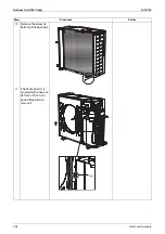
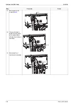
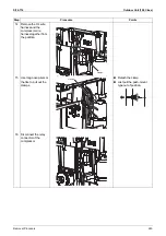
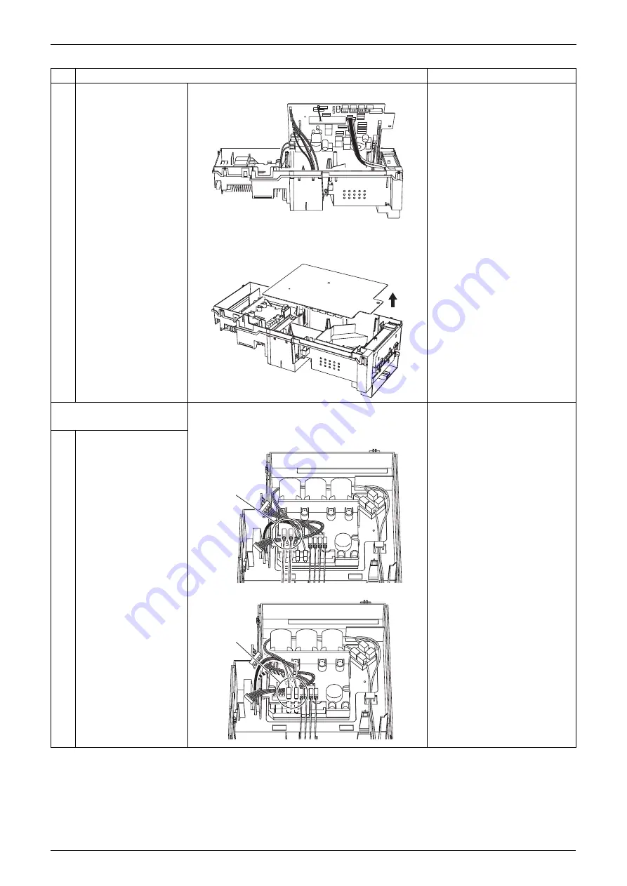
Disconnect the
connectors one by one
starting from your side.
z
Connectors S33 & S71:
For inverter PCB
z
Connectors S31 & S32:
For SPM PCB
z
Connectors S51 & S101:
For display PCB
z
Connector S10: For relay
PCB
z
Connectors H1/H2: For DB
(diode bridge), power wire
harnesses AC1 (red) and
AC2 (black)
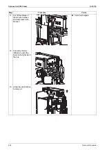
5
Remove the control
PCB.
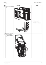
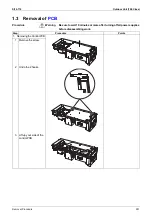
2. Removing the inverter
PCB
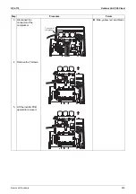
Connector L1/L2
1
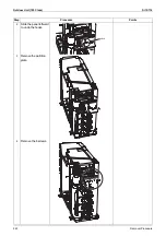
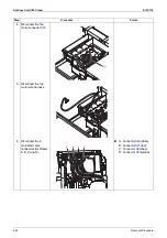
Disconnect the reactor
wire harness connector.
2
Disconnect the rectifier
stack connector.
Black and red
Step
Procedure
Points
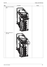
Reactor wire
harness connector
Rectifier stack
connector

