IM 1038 • VAV ACTUATOR ROOM SENSOR 4
www .DaikinApplied .com
I
nstallatIon
I
nstallatIon
The following section describes how to field install a new
BACnet VAV Actuator Room Sensor . Expected Install Time:
20 minutes
CAUTION
Electrostatic discharge hazard. Can cause equipment
damage.
This equipment contains sensitive electronic components that
may be damaged by electrostatic discharge from your hands .
Before you handle a communications module, you need to
touch a grounded object, such as the metal enclosure, in
order to discharge the electrostatic potential in your body .
Required Tools and Materials
• Phillips sizes 1 and 2 screwdrivers
•
Small and medium flat-blade screwdrivers
• 1/16-inch hex key
• Medium-duty electric drill
• 3/16-inch (4 .8 mm) drill bit
• One-inch (25 mm) hole saw
• Small level
• Tape measure
• Marker or pencil
If using non-terminated or damaged cables, you also need:
• Room sensor connector tool (RJ-11 crimping tool)
• Room sensor connector kit (P/N 2508046)
Installing a new BACnet VAV Actuator
Room Sensor
Mounting Information
Always mount the room sensor vertically, on a flat wall.
Locate the room sensor:
•
According to design specifications and local regulations.
• Where the air circulates around it freely (not in recessed
areas or behind doors) .
• Allowing a minimum of 4 inches (10 cm) free space above
and below for proper airflow, the hex bit or passkey tool,
and the computer communication cable .
• Away from drafts caused by doors, windows, outside
walls, air registers, pipes, return air plenums, etc .
•
Away from heat sources such as strong lights, fireplaces,
direct sunlight, etc .
• On an inside wall (preferably), about 5 feet (1 .5 m)
above the finished floor or per code (ANSI, ADA, or local
regulation) .
Drywall Mounting (No Rough-in), Typical
WARNING
For retrofits: Before cutting the cable, make sure it is
disconnected from the Temperature Room Sensor port on the
controller cable end .
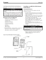
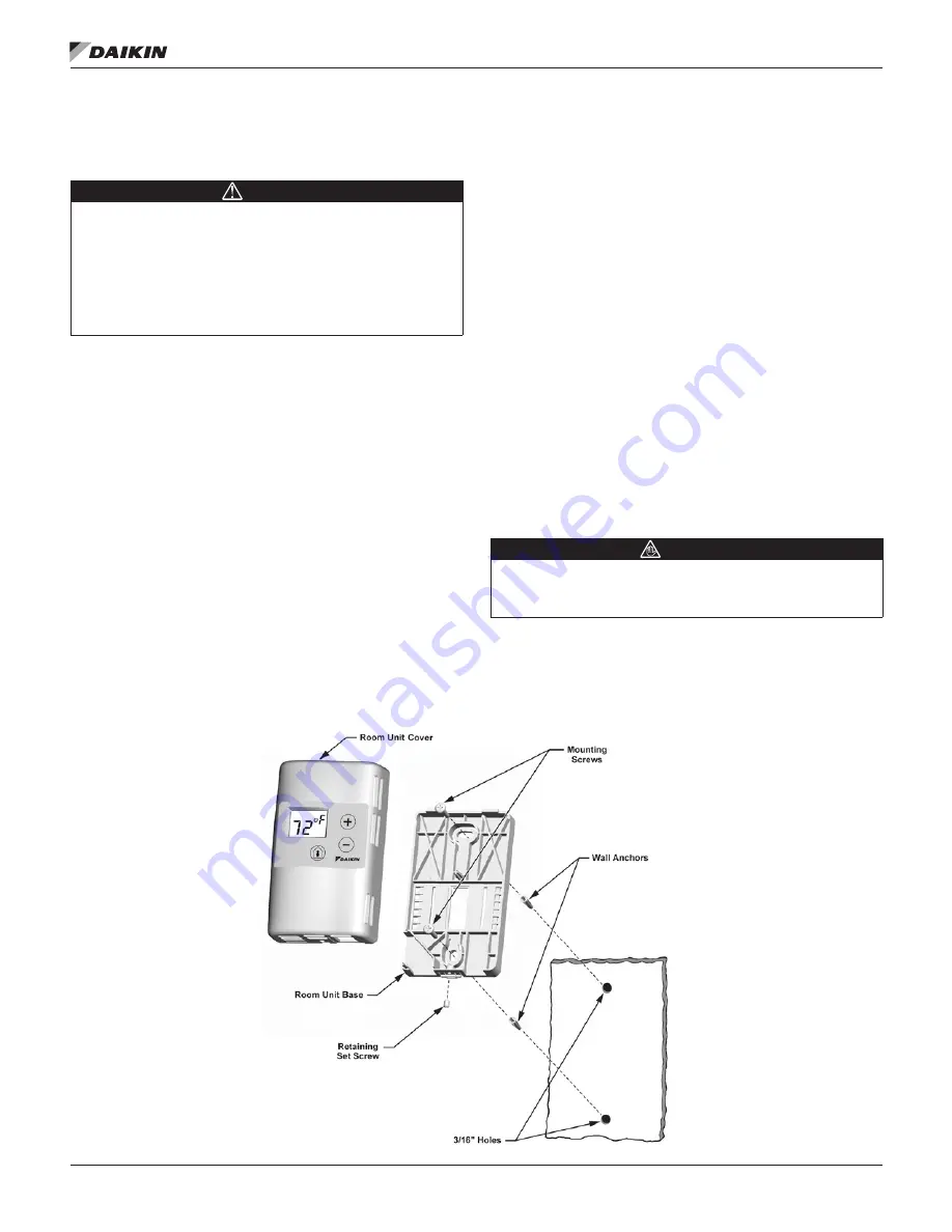
1 . Mark the center (cable) hole and the mounting hole
locations, using the room sensor base plate as a
template . See Figure 2 .
Figure 2: Drywall Mounting (No Rough-in), Typical


