I
nstallatIon
www .DaikinApplied .com
5
IM 1038 • VAV ACTUATOR ROOM SENSOR
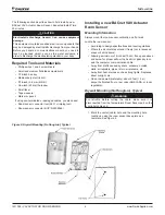
2 . Drill two 3/16-inch (4 .8 mm) mounting holes and mount
the two plastic wall anchors flush to below the wall
surface for stable mounting of the device .
3 . Cut a 1-inch (25 mm) center hole with a hole saw .
4 . Pull about three inches (75 mm) of the cable through the
hole in the base plate .
5 . Mount the room sensor base plate on the wall, noting the
“UP” arrow:
a . Install the two mounting screws provided, but do
not tighten .
b . Level the room sensor base plate for appearance .
c . Tighten the two mounting screws to the room
sensor base plate .
6 . Do one of the following:
a . If the cable is terminated: Inspect the RJ-11
connector for damage .
b . If the cable is non-terminated or if the RJ-11 was
damaged: Cut the cable, leaving about three
inches (75 mm) on the room sensor side of the
drywall, and attach an RJ-11 connector with an RJ-
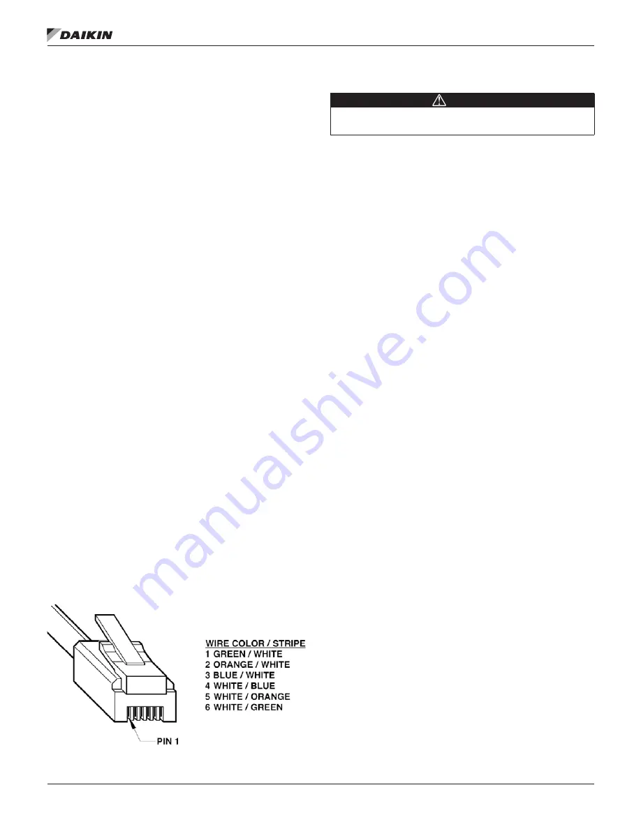
11 crimping tool . On the RJ-11 connectors, ensure
that pin Number 1 connects to the same wire at
each end of the cable . See Figure 3 .
7 . Plug the terminated cable into the RJ-11 connector on the
back of the room sensor’s printed circuit board (PCB) .
8 . Feed the extra cable back through the hole .
9 . Snap the room sensor cover to the room sensor base
plate by first hooking the room sensor front to the top
latches, and then rotating the cover downward until it
latches .
10 . Loosen the safety set screw at the bottom of the base
one or two revolutions to lock the cover to the base .
Be careful not to loosen too far as the screws can be
completely removed from the base .
11 . Connect the room sensor to the Temperature Room
Sensor port on the controller .
This installation is now complete.
Figure 3: Terminating the RJ-11 Connector
Electrical Box and Rough-in Mounting, Typical
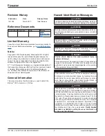
CAUTION
Over-tightening may cause the room sensor base plate to
crack or bend .
1 . If a locator is attached to the rough-in device, remove the
locator by removing the two screws and lightly rocking
the locator to pull it free .
2 . Untie the twist tie and pull about three inches (75 mm) of
the room sensor cable through the hole in the base plate .
3 . Mount the room sensor base plate on the wall, noting the
“UP” arrow:
a . Install the two room sensor mounting screws
provided, but do not tighten .
b . Level the room sensor base plate for appearance
only .
c . Tighten the two mounting screws to the room
sensor base plate .
4 . Continue with Drywall Mounting (No Rough-in), Typical,
Steps 7 through 11 .
This installation is now complete.


