6
1 IM-5WMYJ-0113(2)DAIKIN_EN.indd8 8
1 IM-5WMYJ-0113(2)DAIKIN_EN.indd8 8
6/10/14 10:07:25 AM
6/10/14 10:07:25 AM
English
UNIT INSTALLATION
1
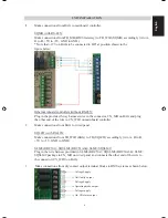
Make connections from BAG to mainboard controller.
SQMB (with RS-485):
Make connections from TB_MB (BMS Gateway) to TB_WIR (SQMB) accordingly (A to A,
B to B, +5V to +5V, GND to GND).
* Note that +12V on BAG to be connected to HP
1
at position shown in the
figure below:
Other mainboard controllers (without RS-485):
Plug in the provided 5-way harness wires to the connector, CN_MB on BAG and plug
the other end of the wire to CN_WIR on mainboard controller.
2
Make connections from BAG to wired panel.
SQLCD (with RS-485):
Make connections from TB_WIR (BAG) to TB (SQLCD) accordingly (A to A, B to B,
+5V to +5V, GND to GND).
SLM8 (BRC51A)/ SQSLM8 (BRC51A64)/ SLM9/ SQSLM9:
Plug in the wire harness provided in SLM8 (BRC51A)/ SQSLM8 (BRC51A64)/ SLM9/
SQSLM9 package to CN_MB on wired panel and connects the other end of the wire to
the connector (CN_WIR) on BAG.
3
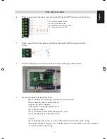
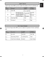
Make connections from dry contact output terminal blocks to BMS system as shown below:
Voltage Supply
Unit faulty output
Voltage Supply
Operating mode output
Voltage supply
On/ Off status output

