Instruction
SiEN18-621
242
System Configuration
Pay attention to running noises, too
•
Are the following places selected?
a. A place that can sufficiently withstand the weight of the
air conditioner with less running noises and vibrations.
b. A place where the hot wind discharged from the air
outlet of outdoor unit and the running noises.
•
Are you sure that there are no obstacles near the air
outlet of the outdoor unit?
Such obstacles may result in declined performance and
increased running noises.
•
If abnormal noises occur in use, stop the operation of
the air conditioner, and then cunsult your dealer or our
service station.
Regarding drainage of drain piping
•
Is the drain piping executed to perform complete
drainage?
If proper drainage is not carried out from the outdoor drain
pipes during air-conditioning operation, chances are that
dust and dirt are clogged in the pipe. This may result in a
water leakage from the indoor unit. Under such
circumstances, stop the operation of the air conditioner,
and then consult your dealer or our service station
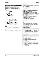
i
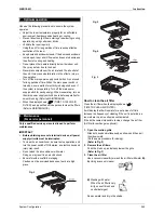
Refer to figure 1 on page [1]
The illustrations in this operating manual correspond to the
remote control format BRC1C type. Although the display
and shape of the buttons on the BRC1B type are slightly
different, they may be operated in the same manner.
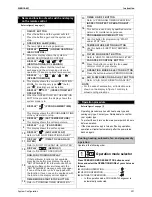
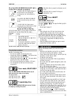
5. Name and function of each switch and display on the
remote control
Thi
s
di
s
pl
a
y
s
how
s
the c
u
rrent OPERATION
MODE. For cooling only type,
“
”
(A
u
to)
a
nd
“
”
(He
a
ting)
a
re not in
s
t
a
lled.
When the IN
S
PECTION/TE
S
T OPERATION
BUTTON i
s
pre
ss
ed, the di
s
pl
a
y
s
how
s
the
s
y
s
tem mode i
s
in.
1
2
3
4
5
“
”
“
”
“
”
“
”
“
”
6
ON/OFF BUTTON
OPERATION LAMP (RED)
The l
a
mp light
s
u
p d
u
ring oper
a
tion.
DI
S
PLAY
“
”
(UNDER CENTRAL-
IZED CONTROL)
When thi
s
di
s
pl
a
y
s
how
s
, the
s
y
s
tem i
s
UNDER CENTRALIZED CONTROL.
DI
S
PLAY
“
”
“
”
“
”
“
”
(VENTILATION/AIR CLEANING)
Thi
s
di
s
pl
a
y
s
how
s
th
a
t the tot
a
l he
a
t
exch
a
nge
a
nd the
a
ir cle
a
ning
u
nit
a
re in
oper
a
tion (The
s
e
a
re option
a
l
a
cce
ss
orie
s
).
DI
S
PLAY
(OPERATION MODE)
DI
S
PLAY
“
TE
S
T
”
(IN
S
PECTION/TE
S
T
OPERATION)
Pre
ss
the
bu
tton
a
nd the
s
y
s
tem will
s
t
a
rt.
Pre
ss
the
bu
tton
a
g
a
in
a
nd the
s
y
s
tem will
s
top.
Thi
s
di
s
pl
a
y
s
how
s
the PROGRAMMED TIME
of the
s
y
s
tem
s
t
a
rt or
s
top.
Thi
s
di
s
pl
a
y
s
how
s
the
s
et temper
a
t
u
re.
Thi
s
di
s
pl
a
y
s
how
s
the
s
et f
a
n
s
peed.
Refer to
“
AIR FLOW DIRECTION ADJU
S
T
”
.
7
8
9
10
DI
S
PLAY
“
”
(PROGRAMMED TIME)
DI
S
PLAY
“
”
(
S
ET TEMPERATURE)
DI
S
PLAY
“
”
(FAN
S
PEED)
DI
S
PLAY
“
”
(AIR FLOW FLAP)
11
12
1
3
14
15
16
17
1
8
19
20
21
22
DI
S
PLAY
“
”
(TIME TO CLEAN AIR
FILTER)
Refer to
“
HOW TO CLEAN THE AIR FILTER
”
.
Refer to
“
DEFRO
S
T OPERATION".
Refer to
“
PROGRAM TIMER OPERATION
”
.
Refer to
“
PROGRAM TIMER OPERATION
”
.
If th
a
t p
a
rtic
u
l
a
r f
u
nction i
s
not
a
v
a
il
ab
le,
pre
ss
ing the
bu
tton m
a
y di
s
pl
a
y the word
s
“
NOT AVAILABLE
”
for
a
few
s
econd
s
.When
r
u
nning m
u
ltiple
u
nit
s
s
im
u
lt
a
neo
us
ly, the
“
NOT AVAILABLE
”
me
ssa
ge will only
a
ppe
a
r
if none of the indoor
u
nit
s
i
s
e
qu
ipped with
the f
u
nction. If even one
u
nit i
s
e
qu
ipped with
the f
u
nction, the di
s
pl
a
y will not
a
ppe
a
r.
DI
S
PLAY
“
”
(DEFRO
S
T)
NON-FUNCTIONING DI
S
PLAY
TIMER MODE
S
TART/
S
TOP BUTTON
TIMER ON/OFF BUTTON
PROGRAMMING TIME BUTTON
TEMPERATURE
S
ETTING BUTTON
FILTER
S
IGN RE
S
ET BUTTON
IN
S
PECTION/TE
S
T OPERATION BUT-
TON
Thi
s
bu
tton i
s
us
ed only
b
y
qua
lified
s
ervice
per
s
on
s
for m
a
inten
a
nce p
u
rpo
s
e
s
.
U
s
e thi
s
bu
tton for progr
a
mming
“S
TART
a
nd/or
S
TOP
”
time.
U
s
e thi
s
bu
tton for
S
ETTING TEMPERA-
TURE.
Refer to
“
HOW TO CLEAN THE AIR FILTER
”
.
Pre
ss
thi
s
bu
tton to
s
elect OPERATION MODE.
Refer to
“
AIR FLOW DIRECTION ADJU
S
T
”
.
Pre
ss
thi
s
bu
tton to
s
elect the f
a
n
s
peed,
HIGH or LOW, of yo
u
r choice.
FAN
S
PEED CONTROL BUTTON
OPERATION MODE
S
ELECTOR BUTTON
AIR FLOW DIRECTION ADJU
S
T BUTTON
NOTE
• For the
sa
ke of expl
a
n
a
tion,
a
ll indic
a
tion
s
a
re
s
hown on the di
s
pl
a
y in fig
u
re 1 contr
a
ry to
a
ct
ua
l r
u
nning
s
it
ua
tion
s
.
Summary of Contents for BPMKS967B2B
Page 1: ...SiENBE18 621 E Series Service Manual Applied Models Super Multi Plus Heat Pump...
Page 12: ...SiENBE18 621 List of Functions 1 Part 1 List of Functions 1 List of Functions 2...
Page 19: ...List of Functions SiENBE18 621 8 List of Functions...
Page 33: ...Specifications SiENBE18 621 22 Specifications...
Page 69: ...Refrigerant Flow for Each Operation Mode SiENBE18 621 58 Refrigerant Circuit...
Page 121: ...Indoor Unit SkyAir Models SiENBE18 621 110 Function...
Page 169: ...Instruction SiENBE18 621 158 System Configuration FTXS 20 25 35C Indoor Unit...
Page 371: ...Method of Replacing The Inverter s Power Transistors Modules SiENBE18 621 360 Troubleshooting...
Page 393: ...SiENBE18 621 vi Index...

