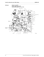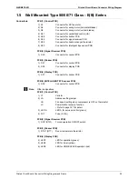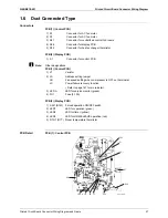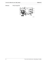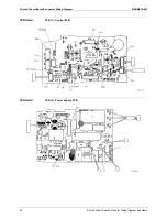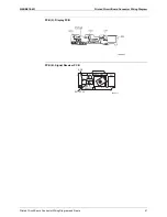
Printed Circuit Board Connector Wiring Diagram
SiENBE18-621
26
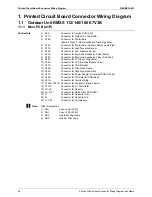
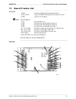
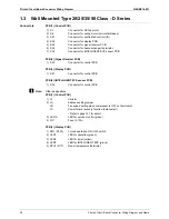
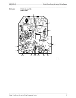
Printed Circuit Board Connector Wiring Diagram and Name
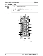
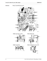
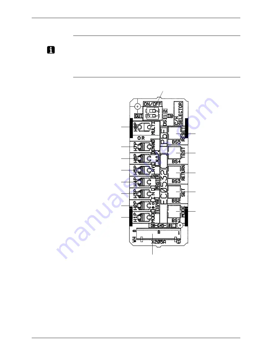
1.1.2 Service PCB (A2P)
Connectors
1) X205A
Connector for Main PCB (A1P)
Note:
Other Designation
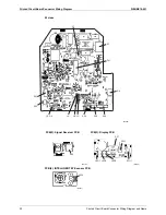
1) H1P to H8P
Service Monitor LED
2) BS1 to BS5
Push Button Switch (Mode, Set, Return, Test, Reset)
3) DS1
DIP Switch
PCB Detail
DS1
H8P
BS5
H7P
H6P
H5P
H4P
H3P
H2P
H1P
X205A
BS4
BS3
BS2
BS1
2P174185
Summary of Contents for BPMKS967B2B
Page 1: ...SiENBE18 621 E Series Service Manual Applied Models Super Multi Plus Heat Pump...
Page 12: ...SiENBE18 621 List of Functions 1 Part 1 List of Functions 1 List of Functions 2...
Page 19: ...List of Functions SiENBE18 621 8 List of Functions...
Page 33: ...Specifications SiENBE18 621 22 Specifications...
Page 69: ...Refrigerant Flow for Each Operation Mode SiENBE18 621 58 Refrigerant Circuit...
Page 121: ...Indoor Unit SkyAir Models SiENBE18 621 110 Function...
Page 169: ...Instruction SiENBE18 621 158 System Configuration FTXS 20 25 35C Indoor Unit...
Page 371: ...Method of Replacing The Inverter s Power Transistors Modules SiENBE18 621 360 Troubleshooting...
Page 393: ...SiENBE18 621 vi Index...

