3
■
English
Display setting
A
/
The wireless remote controller has 2 possible display settings.
The standard setting
A
permanently indicates all operational
items whereas the multi system display setting indicates
operations for a limited period of time after execution of
settings only.
In case the target indoor unit is simultaneously being
controlled;
by another unit in group control,
by a wired remote controller,
by a centralized remote controller.
the indoor unit sometimes does not respond to ON/OFF and
temperature setting commands from the wireless remote
controller.
In order not to confuse the customer with possible
discrepancies between the wireless remote controller
display and the actual operation state of the indoor unit, it
is recommended to set the display on the wireless remote
controller to
in such a control configuration.
Check what setting the customer prefers and adjust the
display setting accordingly.
Display
setting
Remote
controller
display
Result of the display
setting in case the
target indoor unit is
simultaneously being
controlled by more than
1 device
A
: standard All
operational
items are
permanently
displayed.
In the operation mode
changeover, temperature
setting or the like are
carried out from the
wireless remote controller,
the indoor unit rejects the
instruction.
(Signal receiving sound,
1 long beep or 3 short
beeps)
As a result, a display
discrepancy between
the operation state of
the indoor unit and the
indication on the wireless
remote controller display
occurs.
: multi
system
Operations
only remain
displayed
for a short
time after
execution
of the
commands.
Since the indications
on the wireless remote
controller are turned
off, a discrepancy such
as described above no
longer occurs.
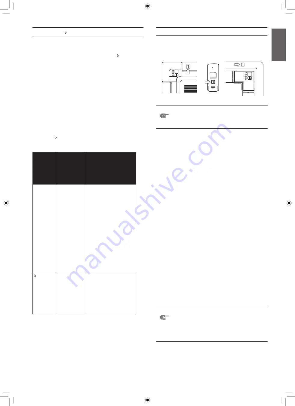
Affix the unit number label
Affix corresponding unit number labels onto both air outlet of
the decoration panel and onto back of the wireless remote
controller.
NOTE Set the Unit No. of the receiver and the wireless
remote controller to be equal. If the settings differ,
the signal from the remote controller cannot be
transmitted.
Installation of the transmitter board
(See figure 2)
1 Electrical wiring box cover
2 Transmitter board
3 Shorter wire harness
4 Longer wire harness
5 Clamp
6 Electrical wiring box
7 Plastic spacer
1 Cut off the power supply.
2 Remove the electrical wiring box cover as described in the
installation manual supplied with the indoor unit.
3 Attach four plastic spacers (7) to the transmitter board (2)
and install it in the electrical wiring box (6).
4 Connect the shorter wire harness from the X2A connector
on transmitter board (2) to X24A connector on the printed
circuit board in the electrical wiring box of indoor unit. Lay
down the shorter wire harness as shown in the figure 2.
5 When the receiver is installed bring the longer wire
harness to the electrical wiring box of indoor unit and
connect it to X1A connector on the transmitter board.
6 Clamp the wire harness by the clamp (5) as shown in the
figure 2.
Installation of the decoration panel
Install the decoration panel as described in the installation
manual supplied with the decoration panel.
NOTE Make sure that the wire harness (longer one) from
the transmitter board is not caught between the
indoor unit and the decoration panel, and between
the ceiling and the decoration panel.
The installation process of the receiver depends
on used decoration panel.
English
01_EN_3P444567-1.indd 3
7/5/2016 11:05:28 AM


