background image

EDUS72-975

Operation Manual

BRC1E71

13

6.3

Names and Functions

3P243520-2C

English

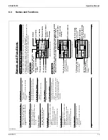
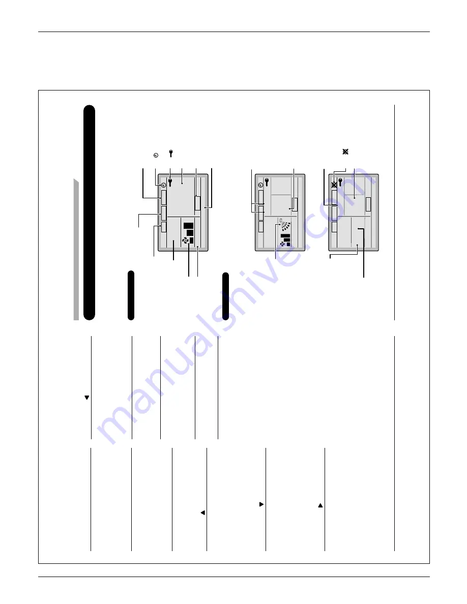
Liquid Crystal Display

T

wo types of liquid crystal display (LCD) are available. 

The standard display is set by default.


Ɣ

Detailed display can be selected in the main menu.  

Ɣ

(See page 37.)

The displayed contents of the screen vary with the operation mode of the indoor unit model. (The  

Ɣ

following display will appear when the indoor unit is in automatic operation.)

  Standard display  

Set to

Cool

Heat

74

F

70

F

Auto

This function is not available

<Standard display example>

6. 

V

e

ntilation

2. 

Fan Speed

1. 

Operation mode

1

1

.Setback

7. 

(     ) display

3. 

Setpoint display

4. 

Stand by for Defrost/

 Hot 

start

5. 

Message

10. 

Changeover controlled by 


the master indoor unit

9.Under centralized 

 control

8. 

(   ) display

AUT

O

ER

V

AIR

PURIFY

CENTRAL CONTROL

MASTER

CONTROLLED

SETBACK

ST

ANDBY

  Detailed Display  

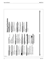
The air fl

 ow direction, clock, and detailed selection items appear on the detailed 


„

display screen in addition to the items appearing on the standard display

.

Cool

Heat

74

F

70

F

Room

Fri

11

:03

A

Set to

74

F

Auto

Return

Setting

14. 

Detailed selection

12. 

Air Flow Direction


(Displayed only when 


the air conditioner is in 

 operation.)

13. 

Current Day/time 


(12/24 hour time 

 display)

<Detailed display example 1>

AUT

O

ER

V

AIR

PURIFY

CENTRAL CONTROL

MASTER

CONTROLLED

SETBACK

ST

ANDBY

Auto

Return

Setting

<Detailed display example 2>

No Air 

Flow 

Direction display 

(with no air flow direction 

settings)


No Fan speed display


(with no fan speed 

 control 

function)

No Detailed item display

(with no detailed items 

selected)

No Clock display 

(when the clock has 

not been set)

15. 

(    ) display

--

:--

CENTRAL CONTROL

MASTER

CONTROLLED

SETBACK

AUT

O

ER

V

AIR

PURIFY

ST

ANDBY

Names and Functions

01_EN_3P243520-2C.indd   6

8/27/2009   1:48:28 PM

English 

5

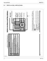
Operation mode selector button
1. 

Press this button to select the operation  

Ɣ

mode of your preference. 

(See page 10.)

A

vailable modes vary with the indoor unit 

model.

Fan speed control button
2. 

Press this button to select the fan speed of  

Ɣ

your preference. 

(See page 1

1.)

A

vailable fan speeds vary with the indoor 

unit model.

Menu/OK button
3. 

Used to indicate the main menu. 

Ɣ

(See page 20 for the menu items.)

Used to enter the selected item. 

Ɣ

Up button 
4. 

Used to raise the setpoint. 

Ɣ

The item above the current selection will be  

Ɣ

highlighted.

(The highlighted items will be scrolled 

continuously when the button is 

continuously pressed.)

Used to change the selected item. 

Ɣ

Down button 
5. 

Used to lower the setpoint. 

Ɣ

The item below the current selection will be  

Ɣ

highlighted.

(The highlighted items will be scrolled 

continuously when the button is 

continuously pressed.)

Used to change the selected item. 

Ɣ

Right button 
6. 

Used to highlight the next items on the  

Ɣ

right-hand side.

Each screen is scrolled in the right-hand  

Ɣ

direction.

Left button 
7. 


Used to highlight the next items on the  

Ɣ

left-hand side.

Each screen is scrolled in the left-hand  

Ɣ

direction.

On/Off button
8. 

Press this button and system will start. 

Ɣ

Press this button again to stop the system. 

Ɣ

Operation lamp (Green)
9. 

This lamp illuminates solid during normal  

Ɣ

operation.

This lamp blinks if a error occurs. 

Ɣ

Cancel button

10. 

Used to return to the previous screen. 

Ɣ

LCD (with backlight)

1

1. 

The backlight will be illuminated for  

Ɣ

approximately 30 seconds by pressing any 

button. 

If two remote controllers are used to control  

Ɣ

a single indoor unit, only the controller to 

be accessed fi

 rst will have backlight 

functionality

.

01_EN_3P243520-2C.indd   5

8/27/2009   1:48:28 PM

Summary of Contents for BRC1E71

Page 1: ...AMERICAS...

Page 2: ...tions 12 6 3 Names and Functions 13 6 4 Basic Operation 15 6 5 Quick Reference 20 6 6 Menu Options 21 6 7 Maintenance 32 6 8 Reference Information 33 7 Installation Manual 34 7 1 Safety Precautions 34...

Page 3: ...and menu driven method Multilingual Display Available for selection of 3 languages to display arbitrarily Other Features Wide variety of functions to meet customer needs such as schedule setting 1 1...

Page 4: ...ure of button allocation for each function the number of buttons has been decreased from 15 to 9 Can intuitively handle frequently performed basic operations 1 Large text display 2 Large buttons 3 Bac...

Page 5: ...ion with arrow keys and menu driven system Available for simple operation with arrow keys and menu driven system Press Menu OK button to change the screen and then the main menu appears Select the ite...

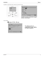
Page 6: ...71 5 Available for simple operation with arrow keys and menu driven system Guide on display The item you wish to set can be changed with up or down button The display gives an explanation of each sett...

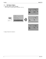
Page 7: ...atures EDUS72 975 6 BRC1E71 1 4 Multilingual Display Available for display in 3 different languages Always available for switching display by selecting from main menu 3 languages English French Spanis...

Page 8: ...EDUS72 975 Features BRC1E71 7 1 5 Other Features...

Page 9: ...unit with 2 remote controllers the remote controller operated first turns the backlight on When controlling 2 remote controllers the following functions cannot be set with the sub remote controller 1...

Page 10: ...ouch Controller DCS601C71 intelligent Manager DAM602A71 72 BACnet Gateway DMS502B71 Central remote controller DCS302C71 Unified ON OFF controller DCS301C71 Schedule timer DST301BA61 Residential centra...

Page 11: ...ions EDUS72 975 10 BRC1E71 4 Dimensions 5 Applicable Models 5 1 Applicable Models 3D065275 Applicable Indoor unit VRV All models that can be connected BRC1D71 SkyAir All models that can be connected B...

Page 12: ...ocks or re Consult your Daikin dealer to relocate or for any reinstallation Do not use ammable materials e g hairspray or insecticide near the remote controller Do not clean the product with organic s...

Page 13: ...cel button 9 Operation lamp 11 LCD with backlight 4 Up button 5 Down button 6 Right button 7 Left button 1 Operation mode selector button 01_EN_3P243520 2C indd 4 8 27 2009 1 48 27 PM English 3 Items...

Page 14: ...NTROL MASTER CONTROLLED SETBACK AUTO ERV AIR PURIFY STANDBY Names and Functions 01_EN_3P243520 2C indd 6 8 27 2009 1 48 28 PM English 5 Operation mode selector button 1 Press this button to select the...

Page 15: ...e page 12 If ventilation icon is displayed in this eld Indicates that an energy recovery ventilator is connected For details refer to the Operation Manual of the ERV Message 5 The following messages m...

Page 16: ...ration procedure Explains the sequence of operation for the remote controller Operate the buttons according to the procedure Operation button display Displays the location of buttons to be operated Ho...

Page 17: ...remote controller Dry Mode Preparation For equipment protection purposes apply power to the outdoor units at least six hours before starting the operation of the system The dry mode may not be select...

Page 18: ...etting Press Mode button several times until the Dry mode is selected The dry mode may not be available depending on the type of indoor unit 2 On Off nu K Press On Off button The Operation lamp green...

Page 19: ...74 F Press the Mode Selector button on the remote controller of the indoor unit which is to serve as the cool heat changeover master The remote controller for the changeover master indoor unit is esta...

Page 20: ...tinue pressing Menu OK button for at least four seconds While the backlight is illuminated 01_EN_3P243520 2C indd 18 8 27 2009 1 48 40 PM English 17 3 Cool Return Setting Set to Cool 74 F Press the Mo...

Page 21: ...at Sun 29 Settings Set the startup time and operation stop time ON Startup time cooling and heating temperature setpoints can be con gured OFF Operation stop time cooling and heating setback temperatu...

Page 22: ...tailed display mode Display mode Standard or detailed display Detailed display provides the choice to display between Room Temp Outside Air Temp System or None 37 Current Settings Used to display a li...

Page 23: ...desired air ow direction Press Menu OK button to return to the basic screen 01_EN_3P243520 2C indd 24 8 27 2009 1 48 47 PM English 23 Air Flow Direction Con guring Air Flow Direction Operation 1 Sett...

Page 24: ...tion High Press the buttons to toggle between the Low and High settings Only modes that can be set are displayed 01_EN_3P243520 2C indd 26 8 27 2009 1 48 49 PM English 25 Operational Details and Funct...

Page 25: ...Press buttons to select Yes and press Menu OK button The date time screen will appear Set the current year month day and time See clock settings on page 39 2 Setting Schedule Enable Disable Daily Pat...

Page 26: ...press of buttons moves the numbers by 1 hour or 1 minute 01_EN_3P243520 2C indd 30 8 27 2009 1 48 53 PM English 29 Daily Patterns Operation 1 Setting Schedule Enable Disable Daily Patterns Settings 2...

Page 27: ...F settings ON or OFF changes in sequence when buttons are pressed ON The temperature setpoints can be con gured OFF The setback temperature setpoints can be con gured The temperature setpoints and set...

Page 28: ...n 1 Setting Main Menu Air Flow Direction Ventilation Schedule Off Timer Celsius Fahrenheit Maintenance Information 1 2 Display the main menu screen See page 22 Press buttons to select the Off Timer on...

Page 29: ...PM English 35 Maintenance Information Displaying the service contact and model information Operation 1 Setting Main Menu Air Flow Direction Ventilation Schedule Off Timer Celsius Fahrenheit Maintenan...

Page 30: ...at is detected may be affected by factors such as the location of the unit for example if it is in direct sunlight and unit operation during defrosting After setting press Menu OK button to con rm set...

Page 31: ...ly 01_EN_3P243520 2C indd 40 8 27 2009 1 49 02 PM English 39 Current Settings Manipulating the current settings Operation 1 Setting Main Menu Configuration Current Settings Clock Calendar Daylight Sav...

Page 32: ...nu screen Language Selectable Languages Operation 1 Setting Main Menu Configuration Current Settings Clock Calendar Daylight Saving Time Language 2 2 Display the main menu screen See page 22 Press but...

Page 33: ...with a dry cloth Note Do not use any paint thinner organic solvent or strong acid 01_EN_3P243520 2C indd 44 8 27 2009 1 49 06 PM English 43 2 Setting Language English Press buttons to select the prefe...

Page 34: ...e Contact your Daikin dealer 01_EN_3P243520 2C indd 46 8 27 2009 1 49 07 PM English 45 Error Code Display Contact your Daikin dealer in the following cases Operation 1 Cool Set to Cool 74 F Error Pres...

Page 35: ...l must carry out the installation work Consult your Daikin dealer regarding relocation and reinstallation of the remote controller Improper installation work may result in leakage electric shocks or r...

Page 36: ...ical shocks or re Do not touch the remote controller buttons with wet ngers Touching the buttons with wet ngers can cause an electric shock Do not install the remote controller in the following locati...

Page 37: ...achment point by using furnished clamping material Clamp 01_EN_3P243521 2B indd 6 8 27 2009 2 00 09 PM English 5 Determine the location where the cabling will enter the 3 4 remote controller back left...

Page 38: ...ood screws F3 5 16mm Switch box installation 3 6 2 Secure by using attached small screws 2 pcs Small screws M4 16mm Switch box field supply Use optional accessory KJB211A Switch box for two units with...

Page 39: ...point temperature Items below the currently selected item will be highlighted The highlighted items will be scrolled continuously when the button is pressed continuously Used to change the selected it...

Page 40: ...e Operation mode selector button of sub remote controller side Checking the connection Please stand by Off reminder Timer Sub RC Basic screen 2 5 Set temperature 28 C Fan Return Press the menu button...

Page 41: ...the settings Field Settings Yes No Press Menu OK button Setting con rmation 01_EN_3P243521 2B indd 14 8 27 2009 2 00 14 PM English 13 Field Settings 6 6 1 Press and hold Cancel button for 4 seconds o...

Page 42: ...ing 1 3 Service Settings Test Operation Maintenance Contact Field Settings Energy Saving Options Prohibit Buttons Min Setpoints Differential Press Menu OK button Basic screen 01_EN_3P243521 2B indd 16...

Page 43: ...f operation is not possible due to a malfunction refer to following Failure diagnosis method After the test operation nishes check that error code history is not displayed in the Maintenance Informati...

Page 44: ...e 12H 24H Clock Press Menu OK button 01_EN_3P243521 2B indd 20 8 27 2009 2 00 18 PM English 19 Entering Maintenance Contact 9 Information Registration of the maintenance contact 9 1 Press and hold Can...

Page 45: ...needed Language 12 12 1 Press Menu OK button in the basic screen Main menu is displayed Select Language in the main menu press Menu OK button Press 12 2 Up Down buttons to select Language on the langu...

Page 46: ...FS K Specifications designs and other content appearing in this brochure are current as of October 2009 but subject to change without notice 1645 Wallace Drive Suite 110 Carrollton TX75006 info daiki...

Reviews: