background image

5

English

[Precautions in handling remote controller]

Direct the transmitting part of the remote con-
troller to the receiving part of the air conditioner.

If something blocks the transmitting and receiving 
path of the indoor unit and the remote controller as 
curtains, it will not operate.

Transmitting distance is approximately 9 m.

Do not drop or get it wet.

It may be damaged.

Never press the button of the remote controller 
with a hard, pointed object.

The remote controller may be damaged.

Installation site

• It is possible that signals will not be received in 

rooms that have electronic fluorescent lighting. 
Please consult with your local dealer before buy-
ing new fluorescent lights.

• If the remote controller operated some other elec-

trical apparatus, move that machine away or con-
sult your local dealer.

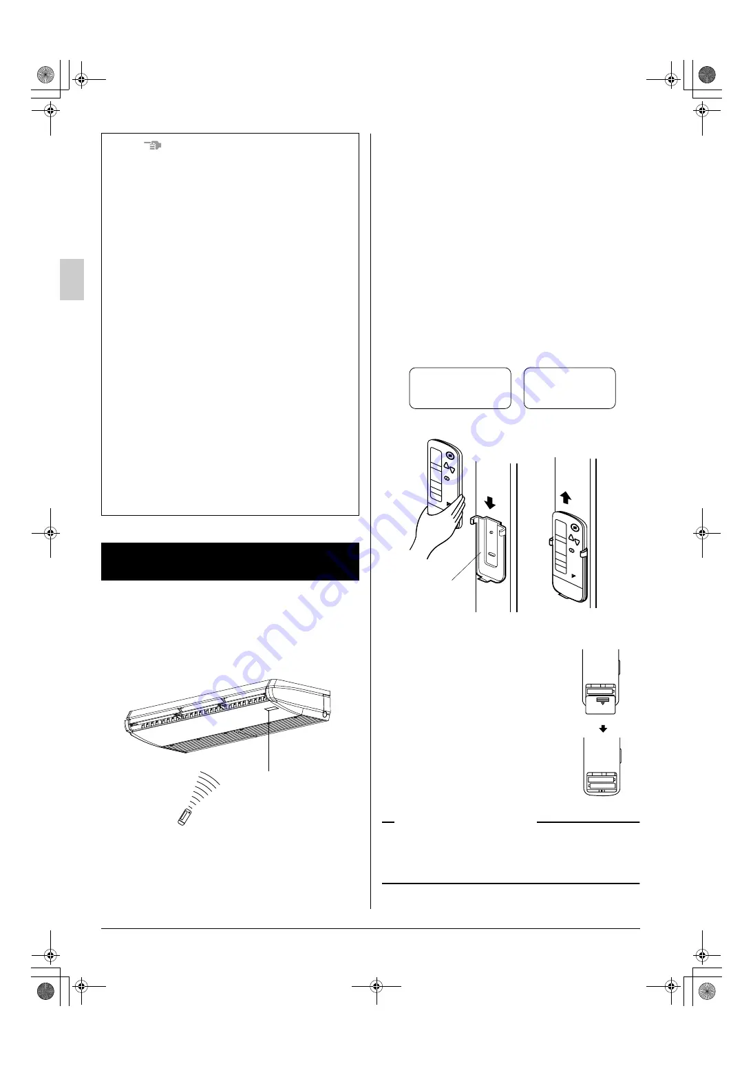
Placing the remote controller in the remote con-
troller holder.

Install the remote controller holder to a wall or a pil-
lar with the attached screw.

How to put the dry batteries

(1)

Remove the back cover of the 
remote controller to the direc-
tion pointed by the arrow mark.

(2)

Put the batteries.
Use two dry cell batteries 
(AAA.LR03 (alkaline)). Put dry 
batteries correctly to fit their (+) 
and (–).

(3)

Close the cover.

When to change batteries

Under normal use, batteries last about a year. How-
ever, change them whenever the indoor unit doesn’t 
respond or responds slowly to commands, or if the 
display becomes dark.

NOTES

• For the sake of explanation, all indications are 

shown on the display in 

Fig. 1

 contrary to actual 

running situations.

Fig. 1-2

 shows the remote controller with the 

front cover opened.

• If the AIR FILTER CLEANING TIME INDICATOR 

LAMP lights up, clean the air filter as explained 
in the operation manual attached to the indoor 
unit.
After cleaning and reinstalling the air filter, press 
the FILTER SIGN RESET BUTTON on the 
remote controller. The AIR FILTER CLEANING 
TIME INDICATOR LAMP on the receiver will go 
out.

• The DEFROST OPERATION LAMP will flash 

when the power is turned on. This is not a mal-
function.

• Do not place the remote controller where subject 

to direct sunlight. The display of the remote con-
troller will get discolored and may fail to display 
information.

[CAUTIONS]
Make sure to turn off the unit and disconnect 
the power supply breaker when taking care 
of the air conditioner.
Unless the power supply is disconnected, it 
may cause electric shocks and injuries.

4. HANDLING FOR WIRELESS 

REMOTE CONTROLLER

Receiver

2 short beeps
from the receiver
indicates that the
transmission is
properly done.

Placing the remote
controller

Slide from above

Remote
controller
holder

Removing the
remote controller

Pull it upward

01_EN_3P302565-2D.fm  Page 5  Sunday, September 30, 2012  1:30 PM

Summary of Contents for BRC7GA56

Page 1: ...ur Il vous expliquera comment vous servir correctement de l appareil et vous guidera en cas de problème Lorsque vous aurez lu le manuel rangez le afin de pouvoir vous y référer ultérieurement Le agradecemos la compra de este acondicionador de aire Daikin Lea cuidadosamente el manual de funcionamiento antes de utilizar el acondicionador de aire Dicho manual le indicará cómo utilizar adecuadamente l...

Page 2: ...er preciso Спасибо за поêóпêó данноãо êондиционера фирмы Daikin До начала работы с êондиционером внимательно изóчите данное рóêоводство по эêсплóатации В нем излаãаются правила надлежащеãо пользования óстройством и приводятся реêомендации пользователю по поисêó и óстранению неисправностей После изóчения рóêоводства сохраните еãо для обращений в бóдóщем Daikin klima satýn aldýðýnýz için teþekkür ed...

Page 3: ... 18 9 1 3 4 6 2 5 7 DOWN FAN UP ON OFF M H L C hr hr TEST MODE TIMER RESERVE CANCEL DOWN UP TEST SWING FAN TIME TEMP ON OFF M H L C hr hr TEST 11 1 2 1 Fig 2 20 22 21 23 24 19 00_CV_3P302565 2D fm Page 3 Saturday September 29 2012 10 54 AM ...

Page 4: ...e all unità interna ΠΡΙΝ ΑΠΟ ΤΗ ΧΡΗΣΗ Αυτü το εγχειρßδιο λειτουργßαò περιÝχει ìüνο οδηγßεò για τη χρÞση του ασýρìατου τηλεχειριστηρßου ÄιαβÜστε επßσηò το εγχειρßδιο λειτουργßαò που συνοδεýει την εσωτερικÞ ìονÜδα για την ασφαλÞ χρÞση του συστÞìατοò και για τη συντÞρηση VOOR GEBRUIK Deze bedieningshandleiding is uitsluitend bedoeld voor gebruik tijdens de instructie over de werking van de afstandsbe...

Page 5: ...sso una struttura specializzata nel riutilizzo riciclaggio e recupero dei materiali Il corretto smaltimento del prodotto eviterà possibili conseguenze negative per l ambiente e la salute dell uomo Per maggiori informazioni contattare l installatore o le autorità locali ΠροϋποθÝσειò απüρριψηò Το συγκεκριìÝνο προϊüν καθþò οι ìπαταρßεò που παρÝχονται ìε το χειριστÞριο επισηìαßνονται ìε αυτü το σýìβολ...

Page 6: ...n off the power to the air conditioner and contact your local dealer Continued operation under such circumstances may result in a failure electric shocks or a fire Consult your local dealer about installation work Doing the work yourself may result in water leak age electric shocks or a fire Consult your local dealer regarding modifi cation repair and maintenance of the air con ditioner Improper w...

Page 7: ... damage to the air conditioner electric shocks or a fire Be sure to use a dedicated power supply for the air conditioner The use of any other power supply may cause heat generation a fire or air conditioner failures Consult your local dealer regarding cleaning the inside of the air conditioner Improper cleaning may cause breakage of plas tic parts water leakage and other damage as well as electric...

Page 8: ...t or catch on a fire due to dust accumulation Never touch the internal parts of the remote controller Do not remove the front panel Touching certain internal parts will cause electric shocks and damage to the remote controller Please consult your local dealer about checking and adjustment of internal parts Do not leave the remote controller wherever there is a risk of wetting If water gets into th...

Page 9: ...ER This sends the signals to the indoor unit 12 TEMPERATURE ADJUSTMENT PROGRAMMING TIMER BUTTON Use this button for temperature setting and programming START and or STOP time Operates with the front cover of the remote controller opened 13 TIMER MODE START STOP BUTTON Refer to page 10 14 TIMER RESERVE CANCEL BUTTON Refer to page 10 15 AIRFLOW DIRECTION ADJUST BUTTON Refer to page 8 9 16 OPERATION ...

Page 10: ...l use batteries last about a year How ever change them whenever the indoor unit doesn t respond or responds slowly to commands or if the display becomes dark NOTES For the sake of explanation all indications are shown on the display in Fig 1 contrary to actual running situations Fig 1 2 shows the remote controller with the front cover opened If the AIR FILTER CLEANING TIME INDICATOR LAMP lights up...

Page 11: ...le to select Refer to Fig 1 1 2 on page 1 OPERATION MODE SELECTOR Press OPERATION MODE SELECTOR BUT TON several times and select the OPERA TION MODE of your choice as follows COOLING OPERATION The recommended temperature setting is 26 to 28 C HEATING OPERATION The recommended temperature setting is 18 to 23 C AUTOMATIC OPERATION In this operation mode COOLING HEATING changeover is automatically co...

Page 12: ...ceiving unit indicator lights Leave it as it stands and wait for a while The remote controller displays the fan speed that is set The air discharge direction becomes horizontal to prevent a draft of cool air to the inhabitants The remote controller will display the set airflow direc tion DEFROST OPERATION Frost removal oper ation for the outdoor unit As the frost on the coil of an outdoor unit inc...

Page 13: ...re Temperature can not be set in the FAN operation In case of automatic operation C The setting is impossible for FAN operation NOTE The setting temperature range of the remote con troller is 16 C to 32 C After settings are changed or operation is turned ON OFF make sure that the receiving tone of the indoor unit makes a beeping sound FAN SPEED CONTROL Press FAN SPEED CONTROL BUTTON Low Middle or ...

Page 14: ...blade is moving may get your fingers pinched The four fins for the left and right airflow direction operate in the same direction as a unit Do not operate adjacent units in the state shown in the drawing This may cause dripping of condensation DISPLAY appears and the airflow direction continuously varies Automatic swing setting Press AIRFLOW DIRECTION ADJUST BUTTON to select the air direction of y...

Page 15: ...BUTTON several times and select the mode on the display The display flashes For setting the timer stop For setting the timer start PROGRAMMING TIMER Press the PROGRAMMING TIMER BUT TON and set the time for stopping or start ing the air conditioner Keep pressing the button to change the setting time continuously The timer can be programmed a maximum of 72 hours 1 TIMER 2 DOWN UP When this button is...

Page 16: ...controller control is operat ing the wireless remote controller displays the OPERATION MODE only If the wired remote controller is used for opera tion the display on the wireless remote controller does not change NOTE Contact your local dealer in case of changing the combination or setting of group control and two remote controller control systems Please do not change the combination and set tings...

Page 17: ...int the cause of the trouble speed ing up the repair Press the INSPECTION TEST OPERATION BUTTON to select the inspection mode appears on display and blinks UNIT No lights up Press PROGRAMMING TIMER BUTTON and change the unit number Press to change the unit number until the indoor unit beeps and perform the following operation accord ing to the number of beeps Number of beeps 3 short beeps Perform ...

Page 18: ...ge 8 Check if the airflow direction is not proper Refer to page 8 9 If the problem is not solved after checking the above points please do not try to repair it yourself In such cases always consult your local dealer At this time please tell the symp tom and model name written on the manufac turer s label Contact your local dealer in the following case WARNING When you detect a burning odor shut OF...

Page 19: ...3P302565 2D EM12A015A 1210 HT 00_CV_3P302565 2D fm Page 6 Saturday September 29 2012 10 54 AM ...

Reviews: