


6 Commissioning
Installation manual
20
C08AA
Daikin hybrid for multi heat pump – heat pump module
4P471756-1C – 2017.10
6
Commissioning
NOTICE
NEVER operate the unit without thermistors and/or
pressure sensors/switches. Burning of the compressor
might result.
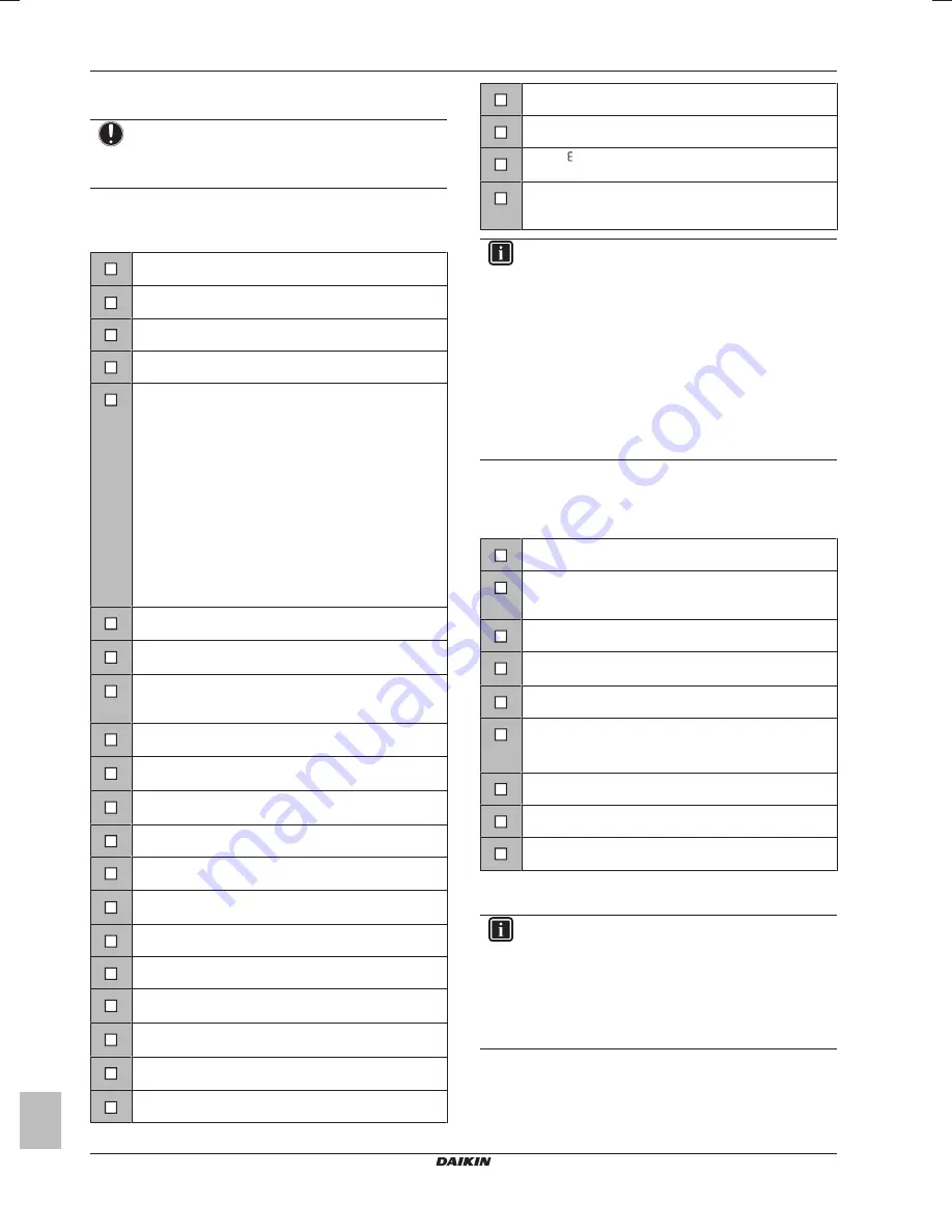
6.1
Checklist before commissioning
Do NOT operate the system before the following checks are OK:
You read the complete installation instructions, as
described in the
installer reference guide
.
The
indoor unit
is properly mounted.
The
outdoor unit
is properly mounted.
The
gas boiler
is properly mounted.
The following
field wiring
has been carried out according
to this document and the applicable legislation:
▪ Between the local supply panel and the outdoor unit
▪ Between indoor unit and outdoor unit
▪ Between the local supply panel and the indoor unit
▪ Between the indoor unit and the valves (if applicable)
▪ Between the indoor unit and the room thermostat (if
applicable)
▪ Between the indoor unit and the domestic hot water
tank (if applicable)
▪ Between the gas boiler and the local supply panel
(only applicable in case of hybrid system)
The
communication cable
between the gas boiler and
the indoor unit is properly mounted.
The system is properly
earthed
and the earth terminals
are tightened.
The
fuses
or locally installed protection devices are
installed according to this document, and have not been
bypassed.
The
power supply voltage
matches the voltage on the
identification label of the unit.
There are NO
loose connections
or damaged electrical
components in the switch box.
There are NO
damaged components
or
squeezed
pipes
on the inside of the indoor and outdoor units.
There are NO
refrigerant leaks
.
The
refrigerant pipes
(gas and liquid) are thermally
insulated.
The correct pipe size is installed and the
pipes
are
properly insulated.
There is NO
water leak
inside the indoor unit.
There is NO
water leak
inside the gas boiler.
There is NO
water leak
in the connection between the
gas boiler and the indoor unit.
The
shut-off valves
are properly installed and fully open
(field supply).
The
stop valves
(gas and liquid) on the outdoor unit are
fully open.
The
air purge
valve is open (at least 2 turns).
The
pressure relief valve
purges water when opened.
The
gas boiler
is switched ON.
Setting . is correctly set on the gas boiler. The setting
must be 0.
The
minimum water volume
is guaranteed in all
conditions. See "To check the water volume" in
"3.2 Preparing water piping" on page 6
.
INFORMATION
The software is equipped with an "installer-on-site" mode
([4‑0E]), that disables automatic operation by the unit. At
first installation, setting [4‑0E] is by default set to "1",
meaning automatic operation is disabled. All protective
functions are then disabled. If the user interface home
pages are off, the unit will NOT operate automatically. To
enable automatic operation and the protective functions,
set [4‑0E] to "0".
36 hours after the first power-on, the unit will automatically
set [4‑0E] to "0", ending "installer-on-site" mode and
enabling the protective functions. If – after first
installation – the installer returns to the site, the installer
has to set [4‑0E] to "1" manually.
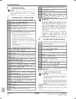
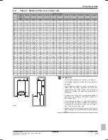
6.2
Checklist during commissioning
The order mentioned in following commissioning checklist MUST be
followed.
To perform a
wiring
check.
The
minimum flow rate
is guaranteed in all conditions.
See "To check the water volume and flow rate" in
"3.2 Preparing water piping" on page 6
.
To perform an
air purge
.
To perform a
test run when the hybrid is in heating
mode
.
To perform an
actuator test run
.
Underfloor screed dryout function
The underfloor screed dryout function is started (if
necessary).
To perform an air purge on the
gas supply
.
To perform a test run on the
gas boiler
.
To perform a test run on the
airconditioning DX unit in
cooling mode.
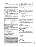
6.2.1
To perform a wiring error check
INFORMATION
▪ You only have to perform a wiring error check if you are
not sure that the electrical wiring and piping is
connected correctly.
▪ If you perform a wiring error check, the hybrid for multi
indoor unit will not operate by heat pump for 72 hours.
During this time, the gas boiler will take over the hybrid
operation.
Prerequisite:
Indoor and outdoor unit must be installed and
connected.
Prerequisite:
Make sure that the water temperature in the system is
>25°C.
1
Heat up the water temperature in the system >25°C.


