background image

8 Technical data

Installation manual

30

C08AA

Daikin hybrid for multi heat pump – heat pump module

4P471756-1C – 2017.10

8.5

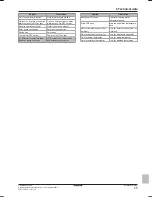
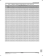
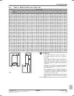
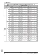
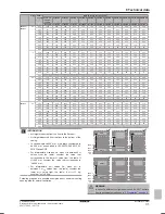
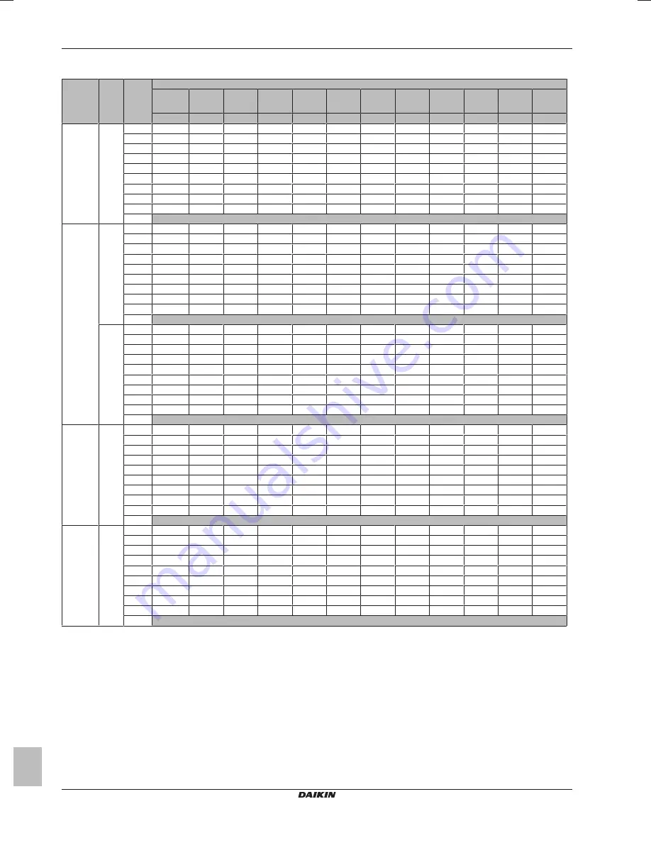
Table 3 – Minimum venting opening area for natural ventilation: indoor unit

m

c

 (kg)

dm=m

c

m

max

 (kg)

Minimum venting opening area (cm

2

)

H=500 mm,

600 mm,

700 mm

H=800 mm

H=900 mm

H=1000 mm H=1100 mm H=1200 mm H=1300 mm H=1400 mm H=1500 mm H=1600 mm H=1700 mm H=1800 mm

h=600 mm

h=700 mm

h=800 mm

h=900 mm

h=1000 mm h=1100 mm h=1200 mm h=1300 mm h=1400 mm h=1500 mm h=1600 mm h=1700 mm

3MXM52

1.8

1.62

659

610

571

538

511

487

466

448

432

417

404

392

1.44

586

542

507

478

454

433

414

398

384

371

359

348

1.26

513

475

444

419

397

379

363

348

336

324

314

305

1.08

440

407

381

359

341

325

311

299

288

278

269

261

0.90

378

339

317

299

284

271

259

249

240

232

225

218

0.72

331

284

254

239

227

217

207

199

192

186

180

174

0.54

268

230

201

180

171

163

156

150

144

139

135

131

0.36

191

164

144

128

115

109

104

100

96

93

90

87

0.18

102

87

76

68

61

56

52

50

48

47

45

44

0.00


4MXM68

2

1.80

732

678

634

598

567

541

518

498

480

463

449

435

1.60

651

603

564

532

504

481

460

442

426

412

399

387

1.40

570

527

493

465

441

421

403

387

373

360

349

339

1.20

488

452

423

399

378

361

345

332

320

309

299

290

1.00

442

379

353

332

315

301

288

277

267

258

249

242

0.80

388

332

291

266

252

241

230

221

213

206

200

194

0.60

314

269

236

210

189

181

173

166

160

155

150

145

0.40

224

192

168

150

135

122

115

111

107

103

100

97

0.20

119

102

89

80

72

65

60

56

54

52

50

49

0.00

2.2

1.98

805

746

698

658

624

595

570

547

527

510

493

479

1.76

716

663

620

585

555

529

506

487

469

453

439

426

1.54

627

580

543

512

485

463

443

426

410

396

384

372

1.32

548

497

465

439

416

397

380

365

352

340

329

319

1.10

510

437

388

366

347

331

317

304

293

283

274

266

0.88

447

383

336

298

278

265

253

244

235

227

220

213

0.66

362

311

272

242

218

199

190

183

176

170

165

160

0.44

258

222

194

172

155

141

129

122

118

114

110

107

0.22

137

118

103

92

83

75

69

64

59

57

55

54

0.00


5MXM90

2.4

2.16

879

813

761

717

681

649

621

597

575

556

538

522

1.92

781

723

676

638

605

577

552

531

511

494

478

464

1.68

683

633

592

558

530

505

483

464

448

432

419

406

1.44

624

542

507

478

454

433

414

398

384

371

359

348

1.20

581

498

436

399

378

361

345

332

320

309

299

290

0.96

510

437

382

340

306

289

276

266

256

247

239

232

0.72

413

354

310

275

248

225

207

199

192

186

180

174

0.48

294

252

221

196

177

161

147

136

128

124

120

116

0.24

156

134

117

104

94

86

78

72

67

63

60

58

0.00


5MXM90

2.6

2.34

952

881

824

777

737

703

673

647

623

602

583

566

2.08

846

783

733

691

655

625

598

575

554

535

518

503

1.82

740

685

641

605

574

547

524

503

485

468

454

440

1.56

703

603

550

518

492

469

449

431

416

402

389

377

1.30

655

562

492

437

410

391

374

360

346

335

324

314

1.04

574

492

431

383

345

314

299

288

277

268

259

252

0.78

465

399

349

310

279

254

233

216

208

201

195

189

0.52

332

285

249

221

199

181

166

153

143

134

130

126

0.26

176

151

132

118

106

96

88

82

76

71

66

63

0.00

Summary of Contents for CHYHBH05AA

Page 1: ...Installation manual Daikin hybrid for multi heat pump heat pump module English Installation manual Daikin hybrid for multi heat pump heat pump module CHYHBH05AA CHYHBH08AA ...

Page 2: ...ívány v souladu s našimi pokyny odpovídají následujícím normám nebo normativním dokumentům u skladu sa slijedećim standardom ima ili drugim normativnim dokumentom ima uz uvjet da se oni koriste u skladu s našim uputama 16 17 18 19 20 21 22 23 24 25 megfelelnek az alábbi szabvány ok nak vagy egyéb irányadó dokumentum ok nak ha azokat előírás szerint használják spełniają wymogi następujących norm i ...

Page 3: ...st before commissioning 20 6 2 Checklist during commissioning 20 6 2 1 To perform a wiring error check 20 6 2 2 To check the minimum flow rate 21 6 2 3 To perform an air purge 21 6 2 4 To perform a test run 21 6 2 5 To perform an actuator test run 21 6 2 6 To perform an underfloor heating screed dryout 22 7 Hand over to the user 22 8 Technical data 22 8 1 Piping diagram Indoor unit 23 8 2 Wiring d...

Page 4: ...n guide boiler communication cable and reducer accessory set are located in the upper part of the box The connection pieces for the gas boiler are attached to the water piping 1 Remove the accessories as described in 2 1 1 To unpack the indoor unit on page 4 a b c d e f g h a General safety precautions b Addendum book for optional equipment c Indoor unit installation manual d Operation manual e Qu...

Page 5: ...e area of the top opening must be larger than or equal to the bottom opening The bottom of the top opening must be situated at least 1 5 m above the top of the bottom opening Ventilation openings to the outside are NOT considered suitable ventilation openings the user can block them when it is cold For ventilation opening requirements see Ventilation opening requirements in the chapter Technical d...

Page 6: ...te is guaranteed even if all valves are closed In case the minimum flow rate cannot be reached a flow error 7H will be generated no heating or operation See the installer reference guide for more information Minimum required flow rate 05 08 models 9 l min See the recommended procedure as described in 6 2 Checklist during commissioning on page 20 3 3 Preparing electrical wiring 3 3 1 Overview of el...

Page 7: ...ower screw on the side panel of the switch box 7 Remove the switch box from the unit 8 Hook the switch box to the side of the unit with the hooks foreseen on the switch box 6 6 7 8 4 2 Mounting the indoor unit 4 2 1 To install the indoor unit 1 Put the installation pattern see box on the wall and follow the steps as shown below 2 1 3 2 Fix the wall bracket to the wall with 2 M8 bolts 2 3 Lift the ...

Page 8: ...id connection b Refrigerant gas connection 2 Connect the gas stop valve from the outdoor unit to the refrigerant gas connection of the indoor unit CHYHBH05 08 Liquid piping Ø6 4 mm 1 4 Gas piping Ø15 9 mm 5 8 4 4 Connecting the water piping 4 4 1 Connecting the water piping of the indoor unit To connect the water piping for space heating NOTICE In case of old heating installations it is recommende...

Page 9: ...missioning on page 20 This function should be used to purge the heat exchanger coil of the domestic hot water tank 4 4 3 To fill the domestic hot water tank For installation instructions see the installation manual of the domestic hot water tank 4 4 4 To insulate the water piping The piping in the complete water circuit MUST be insulated to prevent reduction of the heating capacity If the temperat...

Page 10: ...ect the user interface If you use 1 user interface you can install it at the indoor unit for control close to the indoor unit or in the room when used as room thermostat If you use 2 user interfaces you can install 1 user interface at the indoor unit for control close to the indoor unit 1 user interface in the room used as room thermostat Action 1 Connect the user interface cable to the indoor uni...

Page 11: ...X2M X1M 7 5 6 X5M X2M X1M X5M NO NC M2S M2S 7 6 5 2 Fix the cable with cable ties to the cable tie mountings 4 5 5 To connect the domestic hot water pump 1 Connect the domestic hot water pump cable to the appropriate terminals as shown in the illustration below 35 34 X2M X1M X5M 1 M M2P 2 Fix the cable with cable ties to the cable tie mountings 4 5 6 To connect the alarm output 1 Connect the alarm...

Page 12: ...et to configure the safety thermostat Without configuration the indoor unit will ignore the safety thermostat contact 4 6 Finishing the indoor unit installation 4 6 1 To close the indoor unit 1 Close the switch box 2 Mount the side plate to the unit 3 Mount the top plate NOTICE When closing the indoor unit cover make sure that the tightening torque does NOT exceed 4 1 N m Before doing the configur...

Page 13: ...equisite The EKPCCAB kit is required 1 Connect the cable with USB connection to your PC 2 Connect the plug of the cable to X10A on A1P of the switch box of the indoor unit 3 Pay special attention to the position of the plug 2 3 4 5 H J S T To access the most used commands To access the installer settings 1 Set the user permission level to Installer 2 Go to A Installer settings To access the overvi...

Page 14: ...ard will guide you 4 For proper operation of the system the local data on the two user interfaces must be the same If this is NOT the case both user interfaces will display Synchronization Data difference detected Please select action Send data Confirm Adjust 5 Select the required action Send data the user interface you are operating contains the correct data and the data on the other user interfa...

Page 15: ...zard Standard Space heating settings Code Description A 2 1 7 C 07 Unit temperature control 0 LWT control Not applicable 1 Ext RT control Unit operation is decided by the external thermostat 2 RT control Unit operation is decided based on the ambient temperature of the user interface A 2 1 B N A Only if there are 2 user interfaces User interface location At unit In room A 2 1 8 7 02 Number of wate...

Page 16: ...perature Code Description A 2 2 6 2 D 07 Solar pump station kit 0 No NOT installed 1 Yes Installed A 2 2 6 3 C 09 Alarm output on optional EKRP1HB PCB 0 Normally open The alarm output will be powered when an alarm occurs By setting this value a distinction is made between the detection of an alarm and the detection of a power failure 1 Normally closed The alarm output will NOT be powered when an a...

Page 17: ...cription 7 7 2 1 0 00 0 01 0 02 0 03 Weather dependent curve heating 0 00 0 01 Ta Tt 0 03 0 02 Tt Target leaving water temperature additional Ta Outdoor temperature Pump control Flow target Code Description N A 8 0B Target flow rate during heat pump operation N A 8 0C Target flow rate during hybrid operation N A 8 0D Target flow rate during boiler operation INFORMATION Changing these settings can ...

Page 18: ...ostat control The function will start up the gas boiler when the actual room temperature is 3 C lower than the desired room temperature The large boiler capacity can quickly boost up the room temperature to the desired temperature This can be useful after long periods of absence or after a breakdown of the system Domestic hot water control Only applicable in case an optional domestic hot water tan...

Page 19: ...cation Options DHW operation DHW tank DHW tank type Contact type add Digital I O PCB Demand PCB External kWh meter DHW pump External sensor Leaving water Main Additional Room thermostat Room temp range Room temp offset Ext room sensor offset Operation range Space heating OFF temp Disinfection Disinfection Operation day Start time Temperature target Duration Boiler Equilibrium temp Digital I O PCB ...

Page 20: ... The stop valves gas and liquid on the outdoor unit are fully open The air purge valve is open at least 2 turns The pressure relief valve purges water when opened The gas boiler is switched ON Setting is correctly set on the gas boiler The setting must be 0 The minimum water volume is guaranteed in all conditions See To check the water volume in 3 2 Preparing water piping on page 6 INFORMATION The...

Page 21: ...pages of the user interface If not you can purge air immediately If yes make sure that the room where you want to purge air is sufficiently ventilated Reason Refrigerant might leak into the water circuit and subsequently into the room when you purge air from the heat emitters or collectors 6 2 4 To perform a test run Prerequisite Make sure that the leaving water temperature home page room temperat...

Page 22: ...rost protection will be automatically disabled for 36 hours after the first power on If the screed dryout still needs to be performed after the first 36 hours of power on manually disable room frost protection by setting 2 06 to 0 and KEEP it disabled until the screed dryout has finished Ignoring this notice will result in cracking of the screed NOTICE For the underfloor heating screed dryout to b...

Page 23: ... Domestic hot water hot water IN 16 R1T Plate heat exchanger outlet water thermistor 17 R2T Outlet water thermistor 18 R3T Heat exchanger liquid pipe thermistor 19 R4T Inlet water thermistor 20 Screw connection Screw connection Quick coupling Brazed connection Flare connection 8 2 Wiring diagram Indoor unit See the internal wiring diagram supplied with the unit on the inside of the indoor unit swi...

Page 24: ...ating domestic hot water tank M4S Bypass valve for gas boiler PHC1 Optocoupler input circuit PS Switching power supply Q DI Earth leakage circuit breaker R1T A1P Outlet water heat exchanger thermistor R1T A2P Ambient sensor user interface R1T A3P Ambient sensor On OFF thermostat R2T A1P Outlet gas boiler thermistor R2T A4P External sensor floor or ambient R3T A1P Refrigerant liquid side thermistor...

Page 25: ...onnection Solar pump connection Switch box Switch box Thermo On OFF output Thermo On OFF output 7 External room thermostats and heat pump convector 7 External room thermostats and heat pump convector English Translation Additional LWT zone Additional leaving water temperature zone Main LWT zone Main leaving water temperature zone Only for external sensor floor ambient Only for external sensor floo...

Page 26: ...4 add X2M 1a 3 4 main X2M 1 3 4 add X2M 1a 4 main X2M 1 4 communication 2 core communication 2 core X2 2 4 earth unit power supply 230 V earth Gas boiler 3 core Gas boiler part Heat pump part 4 core In case user interface is relocated In case of signal cable keep minimum distance to power cables 5 cm Field supply Optional part External room thermostat Heat pump convector main and or additional zon...

Page 27: ... 05 3 31 3 56 3 82 4 07 4 33 21 1 56 1 83 2 09 2 35 2 61 2 87 3 13 3 39 3 65 3 91 4 17 4 43 22 1 60 1 87 2 13 2 40 2 67 2 94 3 20 3 47 3 74 4 00 4 27 4 54 23 1 64 1 91 2 18 2 46 2 73 3 00 3 27 3 55 3 82 4 09 4 37 4 64 24 1 67 1 95 2 23 2 51 2 79 3 07 3 34 3 62 3 90 4 18 4 46 4 74 25 1 71 1 99 2 28 2 56 2 84 3 13 3 41 3 70 3 98 4 27 4 55 4 84 26 1 74 2 03 2 32 2 61 2 90 3 19 3 48 3 77 4 06 4 35 4 6...

Page 28: ...hen H is between 2 H values from the table consider the value that corresponds to the lower H value from the table If H 950 mm consider the value that corresponds to H 900 mm In cases where H 600 mm h is always considered to be 600 mm as specified in IEC 60335 2 40 2013 A1 2016 clause GG2 For intermediate Aroom values i e when Aroom is between 2 Aroom values from the table consider the lower Aroom...

Page 29: ...2 13 77 11 15 9 22 7 74 6 60 5 91 5 52 5 17 4 87 2 00 34 32 25 22 19 31 15 25 12 36 10 21 8 58 7 31 6 30 5 81 5 45 5 13 2 10 37 84 27 80 21 29 16 82 13 62 11 26 9 46 8 06 6 95 6 10 5 72 5 38 2 20 41 53 30 51 23 36 18 46 14 95 12 36 10 38 8 85 7 63 6 64 5 99 5 64 2 30 45 39 33 35 25 53 20 17 16 34 13 50 11 35 9 67 8 34 7 26 6 38 5 90 2 40 49 42 36 31 27 80 21 97 17 79 14 70 12 36 10 53 9 08 7 91 6 ...

Page 30: ...0 224 192 168 150 135 122 115 111 107 103 100 97 0 20 119 102 89 80 72 65 60 56 54 52 50 49 0 00 2 2 1 98 805 746 698 658 624 595 570 547 527 510 493 479 1 76 716 663 620 585 555 529 506 487 469 453 439 426 1 54 627 580 543 512 485 463 443 426 410 396 384 372 1 32 548 497 465 439 416 397 380 365 352 340 329 319 1 10 510 437 388 366 347 331 317 304 293 283 274 266 0 88 447 383 336 298 278 265 253 2...

Page 31: ...1 1 92 960 823 720 640 605 577 552 531 511 494 478 464 1 60 895 767 671 597 537 488 460 442 426 412 399 387 1 28 784 672 588 523 471 428 392 362 341 330 319 310 0 96 635 545 477 424 381 347 318 294 273 254 239 232 0 64 453 388 340 302 272 247 227 209 194 181 170 160 0 32 240 206 180 160 144 131 120 111 103 96 90 85 0 00 5MXM90 3 3 2 97 1208 1118 1046 986 936 892 854 821 791 764 740 718 2 64 1074 9...

Page 32: ...4P471756 1C 2017 10 Copyright 2016 Daikin 4P471756 1 C 00000002 ...

Reviews: