background image

cm-clic-cf-eng

www.clima-flex.com

12

COMMUNICATION PROTOCOL

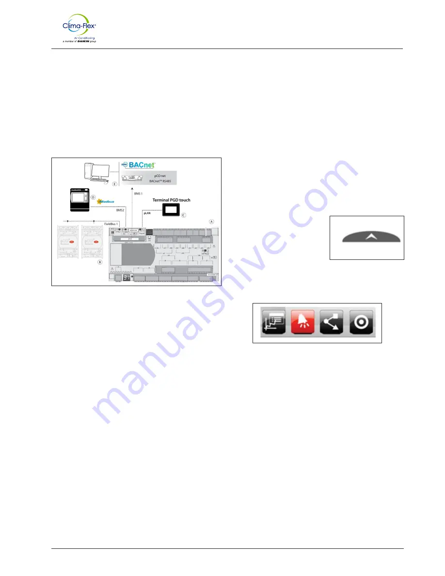
The pCO has 4 independent communication ports configured as 

follows:

•  pLAN: Communicates with the pGD touch terminal using the Modbus 

RTU protocol “Son”.

•  Fieldbus 1: Communicates with the Expansion Modules (located in the 

“Child” units) using the Modbus “Mother” protocol.

•  BMS1: Communicates with a supervisory system using the BACnet* 

protocol (License required).

•  BMS2: Communicates with an external supervisory system such as 

PlanWatch Pro using the Modbus RTU “Child” protocol.

Note:

 The BMS1 port requires a communication card (pCOnet 

to  BACnet  MS/TP  or  pCOweb  for  BACnet  IP). 

The 

programming of the logic packet in the switching 

protocol is also required.

An FLG-Modbus can also be connected to connect a BACnet 

MS/TP.

ALARMS

The alarms that may occur, depending on the initial configuration 

are:

•  Sensor Failure Alarms: If a sensor is detected as disconnected or 

broken, the algorithm being used will be disabled. If it is the head 

injection sensor that was detected, the units will work in “Independent” 

mode automatically.

•  Phase Fault Alarm: Activated by a digital input. Motor protection is a 

high priority alarm and stops all machine functions. It is reset manually.

•  No Flow” Alarm: This alarm is a high priority alarm and stops all 

machine functions. It is manually reset.

•  Freeze Alarm: If the sensor temperature is below the programmed 

threshold, this alarm will be activated. This condition stops all 

functions of the equipment in question. This alarm automatically resets 

once the temperature exceeds the reset value and will keep the unit in 

reset mode (No power for operation for the programmed time.

•  Water Freeze Alarm: Same case as the freeze alarm, but in this alarm, 

the injection sensor reading is considered.

•  High Pressure Alarm: It is triggered by a Digital input. This alarm is 

a high priority event and stops the compressor operation, however it 

does not disable the pump. It is a manual reset alarm. If it is an air-

cooled unit, a command will be sent to start the condenser fan. To 

restart, keep the unit on high output, the compressor will not start until 

the programmed time has elapsed.

•  Low Pressure Alarm: This is activated by a digital input. This alarm 

stops the compressor of the unit in question. It resets automatically, 

however it keeps the unit in a low performance mode.

•  Disconnect Alarm: If the system contains any “Son” units and any of 

these units are disconnected, this alarm will be activated.

•  High Condenser Temperature Alarm: This alarm is only available when 

the unit is air cooled. The alarm is activated when the condenser 

temperature reading exceeds the limit. No control action is taken.

•  Condenser Flow Alarm: This alarm functions like the main Flow alarm; 

it is activated only when the cooling system is water cooled.

•  Lack of Refrigerant Alarm: This alarm is activated when a start 

command is sent due to cooling demand, and the injection temperature 

sensor detects a change in temperature for a period of time. This alarm 

does not take Control actions and can be deactivated by the user.

USER INTERFACE

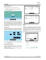
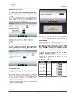
Navigation Bar

The Navigation bar is found on every 

screen of the system. It appears 

and disappears automatically by 

pressing the tab at the bottom, as 

shown in Fig. 11.

  Figure 11. On-screen navigation 

bar

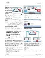
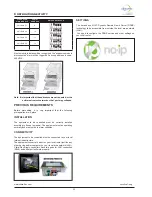
When the tab is pressed the navigation menu will be displayed, as 

in Fig. 12.

  Figure 12. Example of navigation bar on the main screen

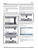
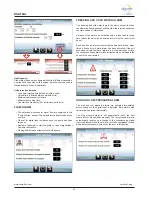
The navigation menu changes the access icons depending on 

the context where the user is in the system. Potential navigation 

buttons are shown below.

Control

Summary of Contents for Clima-Flex CLIC Series

Page 1: ...Control Manual CLIC Series Air Cooled Fixed Compressor Chilled Ice Water Generator Unit Model 25 to 250 TR Refrigerant HFC 410A 50 60 Hz CM Group Chiller Part Number CM CLIC Date 8 November 2022...

Page 2: ...Clima Flex product at the time of publication and we reserve the right to make changes in design and construction at any time without notice Manufactured in an ISO 9001 certified facility Safety Warni...

Page 3: ...ntial choking danger as the refrigerant will displace air in the immediate area Be sure to follow all applicable published industry related standards and local state and federal statutes regulations a...

Page 4: ...ITS 1 Stand alone 2 2 units 3 3 units 4 4 units 5 5 units 6 6 units 7 7 units 8 8 units 9 units 10 10 units CONDENSER FAN A Axial Fixed ANTICORROSION C Coat in Condenser I Coat in Components M Total C...

Page 5: ...commitment to our customers and stakeholders our equipment comes with a 1 year major warranty after start up Our units use R410A refrigerant which is harmless to the ozone layer and is non toxic and...

Page 6: ...er based synthetic coating with ES2 pigment applied to all areas of the coating surface with no bridging of material between fins Therefore ES2 pigments are suitable for even the most corrosive enviro...

Page 7: ...nal belongs to the family of touch screens designed to make the interaction with the pCO system controls easier and more intuitive The electronic technology used and the new 64 000 color display allow...

Page 8: ...ed flow rate and has NO and NC NPN outputs HIGH LOW PRESSURE CONTROL ACB LCB is a small disc type pressure control for use in refrigeration and air conditioning systems As standard it is equipped with...

Page 9: ...OND STAGE NTC NO8 REVERSIBLE VALVE NTC PORT CO AIR HP AIR CO WATER HP WATER TYPE Y1 INVERTER SSR INVERTER SSR 0 10 V PORT CO AIR HP AIR CO WATER HP WATER TYPE B1 INJECTION INJECTION NTC B2 RETURN RETU...

Page 10: ...ital input for this value is a virtual input with a value of 1 or OK if the water flow is acceptable REGULATION Temperature control can be implemented in different ways always taking into account the...

Page 11: ...demand In any configuration the Mother compressor whose capacity is controlled by a drive or a flow valve is the first to start and the last to stop An example of global demand management by starting...

Page 12: ...he freeze alarm but in this alarm the injection sensor reading is considered High Pressure Alarm It is triggered by a Digital input This alarm is a high priority event and stops the compressor operati...

Page 13: ...ble sends user to Alarms page Home Sends the user to the Main Menu Return to Sends the user to the last accessed page Main Menu Sends the user to the Main Menu Alarm log Sends the user to the Alarm Lo...

Page 14: ...of all units will be displayed The properties of the graphs that can be edited are Duration Time Period and maximum and minimum limits Temperature Ranges MENU On the home screen there is a button to...

Page 15: ...e status of the Compressors Independent the mode of operation Cooling or Heating and the status of the Compressors If the control is in Tandem mode it will also show the overall system demand as well...

Page 16: ...units The rotation logic of the units is also enabled Independent Control Ignores the injection and return sensors on the main unit The injection and return temperature readings of the Mother unit wil...

Page 17: ...splayed there are 2 options regular format Day Month Year or US format Month Day Year Note This section is only available for systems configured as Heat Pump WORK HOUR COUNTER The Hours Worked Counter...

Page 18: ...t PID and set the integral time to 0 INDEPENDENT CONTROL The Independent Control calculates all the parameters that regulate the demand control in each unit independently using the injection temperatu...

Page 19: ...blems in your system such as inefficiency and lack of rated capacity For water heat pumps you will see the condenser sensor do not change the maximum and minimum values these must be configured in the...

Page 20: ...r systems with Heat Pump function 1 Enable Defrost Sequence 2 Enable defrost at controller startup 3 Defrost Interval How often defrost is initiated 4 Defrost activation By temperature by defrost By t...

Page 21: ...ic is the same except that one considers the freezing sensor and the other the injection sensor as the main source of information For each of the alarms an activation value a reset and recovery time w...

Page 22: ...t the initial settings Resetting resets the initial system configuration parameters but does not change any of the other values stored in the controller s memory set points differential alarms etc It...

Page 23: ...in place INSTALLATION The equipment to be controlled must be correctly installed according to its user s manual The equipment must be operating normally and must not be in alarm condition CONNECTIVITY...

Page 24: ...of your local area network LAN Along with the Domain Name your equipment has an IP address assigned to it to be controlled and manipulated from inside LAN of your local area network Domain Name Unidad...

Page 25: ...the connection is made you will probably receive a warning that the connection is not Encrypted please disregard this warning as it is not required or necessary to encrypt control sessions with your c...

Page 26: ...Al_Baja_pres_E7 389 DigitalInput Al_Baja_pres_E8 544 DigitalInput Al_Baja_pres_E9 560 DigitalInput Al_congelamiento_E1 28 DigitalInput Al_congelamiento_E10 579 DigitalInput Al_congelamiento_E2 43 Dig...

Page 27: ...talInput ED_sensor_flujo_E8 609 DigitalInput ED_sensor_flujo_E9 630 DigitalInput ED_sensor_flujo_M 163 DigitalInput H_AP_CompE1 5072 AnalogInput H_AP_CompE10 5424 AnalogInput H_AP_CompE2 5084 AnalogIn...

Page 28: ...Input LoadDown_Countdown 5045 AnalogInput Modo_B_C 235 Coil Modulate_Power_Req 88 AnalogInput ON_OFF 142 DigitalInput on_off2 84 Coil Reset_Als 111 Coil Setpoint_cal 91 Holding Setpoint_enf 9 Holding...

Page 29: ...t Temp_ret_E7 194 AnalogInput Temp_ret_E8 235 AnalogInput Temp_ret_E9 242 AnalogInput Temp_ret_Maestro 52 AnalogInput Ventilador_E1 217 DigitalInput Ventilador_E10 647 DigitalInput Ventilador_E2 221 D...

Page 30: ...cm clic cf eng www clima flex com...

Reviews: