cm-clic-cf-eng
www.clima-flex.com
22
Control
REFRIGERANT ALARM
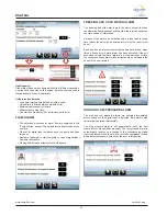
The refrigerant alarm is a user-enabled warning that evaluates the
change in the injection temperature sensor when the compressor
starts running. If it detects any change in the set time, the alarm
is activated.
This alarm will not stop any control process. In this section the
user can enable and disable the alarm, and if applicable, set the
minimum detection range and the maximum time in which this
change must occur to not activate the alarm.
CONDENSING UNIT HIGH TEMPERATURE
ALARM
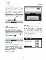
This process will only be enabled if the system is air-cooled.
This alarm is triggered when the condenser temperature sensor
exceeds the value set in this section. This alarm is a warning, so it
does not affect any control process or stop the compressor.
RESTAURATION
In the last section that can be accessed with the Level 3 password,
there is the option to reset the unit to factory settings.
Restore System allows the user to reconfigure the system as a
completely new installation and reset the initial settings. Resetting
resets the initial system configuration parameters, but does not
change any of the other values stored in the controller’s memory
(set points, differential, alarms, etc.).
It is the user’s responsibility to properly configure the system with the new
settings for proper operation of the units.
Note: When the system is reset, the user must restart both
the controller (pCO) and the terminal (pGD Touch).
ADDENDUM
SERIAL ADDRESS OF EXPANSION MODULES
Each “Child” unit uses an expansion module that communicates
via Modbus with the parent (pCO) controller through the Fieldbus1
port of the controller. Consequently, the units need to be configured
with the correct serial address. To avoid errors, the address
is set and fixed when the controller is programmed and cannot
be changed. The only task to be performed by the user is to set
the physical address of the expansion modules by combining 4
“switches” on each expansion module.
The address on the “switches” is set by the 4-bit binary number
they represent. The lower position of the “switches” has a value of
“1” and the opposite is “0”.
The addresses to assign are:
PCOE EXPAN-
SION MODULE
SERIAL
ADDRESS
SWITCHES IN PCOE
CHILD UNIT 1
1
CHILD UNIT 2
2
CHILD UNIT 3
3
CHILD UNIT 4
4


