cm-clic-cf-eng
www.clima-flex.com
7
Control
PCO SYSTEM
The system is designed to handle one unit with capacity control
by means of a drive or a typical unloading valve on a digital fixed
compressor, this is a unit called “Mother” and up to 9 additional
units without capacity control called “Sons” can be added.
FUNCTION
The “Mother” unit is managed directly by the main control, the
pCO. Each “Child” unit is controlled by a pCOE expansion module.
If the units are water-cooled, they require one expansion module
per “Child” unit. Each “Mother” unit is equipped with a 7” pGD
touchscreen terminal.
PCO (CONTROL)
The is an electronically programmable microprocessor-
based controller that is fully compatible (software and hardware) with
the pCO family of products and systems that include programmable
controllers, user terminals, gateways, communication devices and
remote device management.
These devices represent a powerful control system that can be
easily linked with the vast majority of Building Management
Systems (BSM) available on the market.
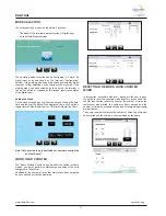
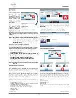
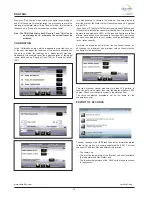
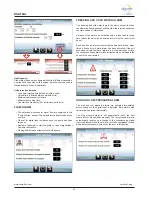
Figure 1. Pco(Control) Optional Equipment
PGD TOUCH (HMI)
The pDG 7” touch screen graphic terminal belongs to the family
of touch screens designed to make the interaction with the
pCO system controls easier and more intuitive. The electronic
technology used and the new 64,000 color display allow for high
image quality and high aesthetic quality.
The touch screen panel also facilitates user-machine interaction by
making it easier to navigate between the different screens.
Table 1. Description of PCO Control Equipment
Table 2. Description of PGD Touch Screen
Figure 2. Pco(Control) Optional Equipment
REF
DESCRIPCIÓN
1
Power connector [G(+), G0(-)].
2
pLAN address setting button and secondary display, LEDs.
3
Universal inputs/outputs
4
+Vdc: Power for active probes
+5 VR Power for radio metric probes
5
Analog Outputs
6
DI: Voltage-free digital inputs
7
Fieldbus connector 1
8
BMS Connector 2
9
Single-pole valve connectors
10
pLAN plug in connector
11
Connector for pLAN telephone terminal / Download application for program-
ming
12
Digital Relay Outputs
13
Digital Relay Outputs for power on
14
Alternating power supply for "Power on digital relay outputs".
REF
DESCRIPTION
1
SD card connector
2
Membrane keypad programming
3
Optically Isolated RS485 port
4
Ethernet port 1 (internal switch)
5
Ethernet Port 2 (Internal switch)
6
USB Host Port
7
RS485 port without optical isolation
8
Power Supply
9
Plug-in connector (on the back)


