cm-clic-cf-eng
www.clima-flex.com
8
Control
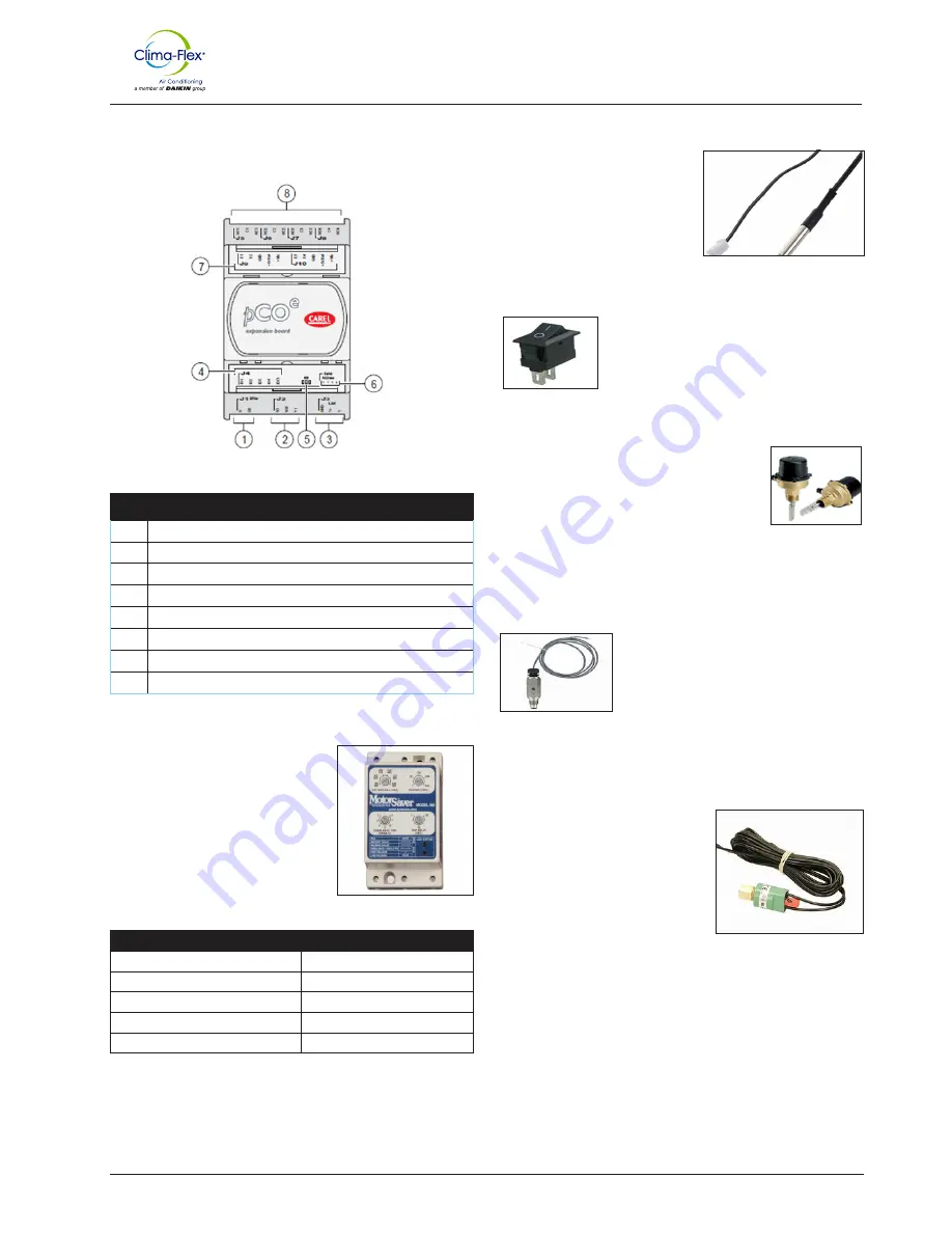
EXPANSION TABLE
MOTOR SAVER
It is designed so that 3-phase loads
are not damaged by power supply
conditions.
• Loss of any of the phases
• Low voltage
• High voltage
• Voltage spikes
• Phase reversal
• Fast cycling
DIAGNOSTIC INDICATOR LIGHTS
REGULAR OPERATION
STEADY GREEN
START DELAY
FLASHING GREEN
INVERSE PHASE
FLASHING RED
UNBALANCED PHASE
LAPSES IN RED
HIGH / LOW VOLTAGE
RED CONSTANT
Table 3. Expansion Table Description
Table 4. Diagnostic Indicator Lights
TEMPERATURE SENSOR
The PT10K NTC Temperature
Sensor is resistant to temperature
changes, the relationship with the
curve is the higher the temperature,
the lower the resistance and vice
versa.
Electrical component that can interrupt the
electrical circuit, interrupting the current or
diverting it from one conductor to another.
VANE FLOW SENSOR
The flow switch comprises a unique paddle
system, the design of which is a paddle located
at the flow end that is pivoted in the center and
a magnet at the opposite end.
THERMAL DISPERSION SENSOR
It is a thermal flow switch that indicates
whether the flow rate is above or below the
user-selected flow rate, and has NO and NC
NPN outputs.
HIGH / LOW PRESSURE CONTROL
ACB / LCB is a small disc type pressure
control for use in refrigeration and air
conditioning systems. As standard, it
is equipped with a contact system with
manual or automatic reset. The control
is robust and reliable in the operation of
different unit types.
Figure 3. Expansion Table or Module
Above this magnet is a reed switch contact, isolated outside the
flow chamber. A second magnet creates the force necessary to
reset the vane back to the zero flow position.
Thanks to its small size, light weight and high degree of protection
it can be placed directly in the refrigeration system where pressure
regulation is required.
The control is available with different settings and pressure
connections to meet customer needs.
All these features reduce installation costs and save space.
It uses a pulsed thermal dispersion measurement technique to
measure the flow rate, whereby the probe is heated above the
process temperature and then cooled to the process temperature.
REF
DESCRIPTION
1
SD card connector
2
Membrane keypad programming
3
Optically Isolated RS485 port
4
Ethernet port 1 (internal switch)
5
Ethernet Port 2 (Internal switch)
6
USB Host Port
7
RS485 port without optical isolation
8
Power Supply
DIGITAL INPUT (REMOTE ON/OFF, OPERATION
MODE: COOLING, HEATING)


