iom-clic-cf-eng
www.clima-flex.com
14
INLET STRAINER GUIDELINES
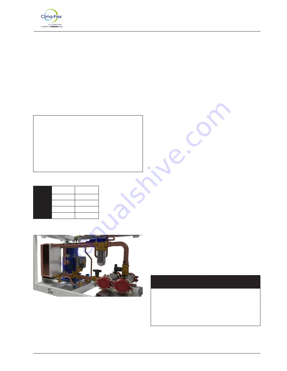
An inlet water filter kit must be installed in the cold water piping
upstream of the evaporator inlet. There are several ways available
to meet this requirement:
1. A factory-installed option is available - models 025 through
250.
2. A field installation kit is shipped loose with the unit and is
available for all unit sizes and consists of:
• Y-type area strainer with 304 stainless steel perforated
basket, slotted pipe connections and strainer cover.
3. A field supplied strainer that meets the specifications and in-
stallation requirements of this manual.
Figure 8. Factory installed strainer
WATER FLOW LIMITATIONS
Constant evaporator flow
Maximum flow rate and pressure drop are based on a 6°F
temperature drop. Flow rates above the maximum values will
result in unacceptable pressure drops and may cause excessive
erosion, which could lead to failure.
Variable evaporator flow
Reducing evaporator flow rate in proportion to load can reduce
system energy consumption. The rate of flow change should be a
maximum of 10 percent of the flow per minute. For example, if the
maximum design flow rate is 200 gpm and is to be reduced to a
flow rate of 140 gpm, the flow change is 60 gpm.
Ten percent of 200 gpm equals a change of 20 gpm per minute,
or a minimum of three minutes to go from the maximum flow to
the desired flow.
If the flow rate falls below the minimum allowable, large reductions
in heat transfer can occur. If the flow rate exceeds the maximum,
excessive pressure drop and tube erosion can occur.
TECHNICAL DATA OF THE STRAINER
•
Head and neck nut:
Brass
•
Filter element:
Polyamide body coated with nylon mesh
•
Filter cup:
Trogamid T 5000 (virtually impact resistant,
pressure wave resistant, permanently transparent, stress
resistant).
• (Brass cup available on request).
•
Working pressure:
PN 16
•
Test pressure:
25 bar
•
Maximum water temperature:
30° C
•
Mesh size:
95-140 μm.
•
Available with and without Rp 1/8/8 pressure gauges.
Table 2.
Flow rates according to DVGW test
DN 20
Rp 3/4
5,0 m3/h
DN 35
Rp 1
7,9 m3/h
DN 32
Rp 11/4
12,0 m3/h
DN 40
Rp 11/2
11.9 m3/h
DN 50
Rp 2
14,9 m3/h
Δp = 0,2 bar:
Installation and Application Information
System water considerations
All chilled water systems need adequate time to recognize a load
change, respond to the change and stabilize to avoid undesirable
compressor short cycling or loss of temperature control.
In air conditioning systems, the potential for short cycling often
occurs when the building load drops below the minimum capacity
of the chiller plant or in tightly coupled systems with very small
water volumes. Some of the aspects that the designer should
consider when studying water volume are the minimum cooling
load, the minimum capacity of the chiller plant during the low-load
period, and the desired cycle time for the compressors. Assuming
there are no sudden loads and the chiller plant has a reasonable
drawdown, the rule of thumb of “water volume in gallons equals
two to three times the chilled water flow rate in gpm” is often used.
A storage tank may have to be added to the system to achieve the
recommended volume.
The quality of water supplied by the owner/occupant/operator/
user to a cooling system should minimize corrosion, scale
buildup, erosion, and biological growth to achieve optimum
efficiency of HVAC equipment without creating a hazard to
operating personnel or the environment. Filters should be used to
protect cooling systems from waterborne debris. Clima Flex is not
responsible for damage caused by waterborne debris or damage
to chiller heat exchangers due to improper water treatment.
Water systems should be cleaned and flushed prior to chiller
installation. Testing and water treatment should be verified during
initial chiller installation/commissioning and should be maintained
on an ongoing basis by water treatment professionals (see limited
product warranty).
!
CAUTION
!
Improper use of detergents, chemicals and additives in the
cooling system water can adversely affect the performance
of the chiller and potentially result in repair costs not covered
under warranty. Any decision to use these products is at
the discretion of the owner/occupant/operator/user, and the
owner/occupant/operator/user assumes full responsibility for
any damage that may occur due to their use.
The minimum flow rate and pressure drop are based on a full
load evaporator temperature drop of 16°F. Evaporator flow rates
below the minimum values may result in laminar flow leading to
low pressure alarms, fouling and poor temperature control (See
pressure drop on page 35).
Summary of Contents for Clima-Flex CLIC Series
Page 39: ...iom clic cf eng www clima flex com 39 Electrical Data...
Page 41: ...iom clic cf eng www clima flex com 41 Electrical Data...
Page 43: ...iom clic cf eng www clima flex com 43 Electrical Data...
Page 45: ...iom clic cf eng www clima flex com 45 Electrical Data...
Page 46: ...iom clic cf eng www clima flex com 46 Electrical Data...
Page 48: ...iom clic cf eng www clima flex com 48 Electrical Data...
Page 53: ...iom clic cf eng www clima flex com 53 R454B Electrical Data Figure 38 RS485 communication...
Page 77: ...iom clic cf eng www clima flex com 77 Clic R454b Unit This unit use the R454B Refrigerant...
Page 117: ...iom clic cf eng www clima flex com 117 THIS PAGE IS INTENTIONALLY LEFT BLANK...
Page 118: ...iom clic cf eng www clima flex com...


