Si18-525B
Field Setting
Test Operation
171
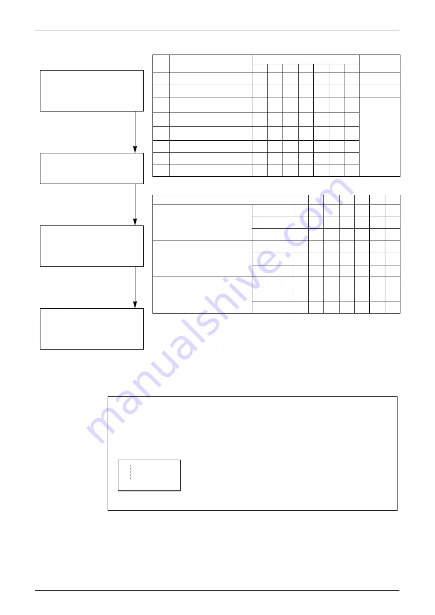
Setting item 0 Display contents of “Various settings”
No.
Setting item
LED display
Data display
H1P
H2P
H3P
H4P
H5P
H6P
H7P
0
Various settings
9 7 7 7 7 7 7
See below
5
Number of connected indoor units
9 7 7 7 8 7 8
Lower 6 digits
14
Contents of malfunction (the
latest)
9 7 7 8 8 8 7
Malfunction
code table
15
Contents of malfunction
(1 cycle before)
9 7 7 8 8 8 8
16
Contents of malfunction
(2 cycle before)
9 7 8 7 7 7 7
20
Contents of retry (the latest)
9 7 8 7 8 7 7
21
Contents of retry (1 cycle before)
9 7 8 7 8 7 8
22
Contents of retry (2 cycle before)
9 7 8 7 8 8 7
Setting item
H1P H2P H3P H4P H5P H6P H7P
Defrost select setting
Short
9 7 7 7 8 7 7
Medium
9 7 7 7 9 7 7
Long
9 7 7 7 7 7 7
Te setting
H
9 7 7 7 7 8 7
M
9 7 7 7 7 9 7
L
9 7 7 7 7 7 7
Tc setting
H
9 7 7 7 7 7 8
M
9 7 7 7 7 7 9
L
9 7 7 7 7 7 7
c. Monitor mode
<Selection of setting item>
<Confirmation on setting contents>
To enter the monitor mode, push the
MODE button (BS1) when in
“Setting mode 1”.
Push the SET button (BS2) and set
the LED display to a setting item.
Push the RETURN button (BS3) to
display different data of set items.
Push the RETURN button (BS3) and
switches to the initial status of
“Monitor mode”.
∗
Push the MODE button (BS1) and
returns to “Setting mode 1”.
(V2765)
Push the SET button and match with the LEDs No. 1 - 15, push the RETURN button, and
enter the data for each setting.
Data such as addresses and number of units is expressed as binary numbers; the two
ways of expressing are as follows:
The No. 5 cool/heat unified address is expressed as a binary
number consisting of the lower 6 digits. (0 - 63)
In the address is 000110 (binary number), which translates to
4 + 2 = 6 (base 10 number). In other words, the address is 6.
9 797997
16 4 1
32 8 2
Summary of Contents for D-Series
Page 1: ...Si18 525B Applied Models Super Multi Plus Cooling only Super Multi Plus Heat Pump D Series ...
Page 33: ...List of Functions Si18 525B 20 List of Functions ...
Page 71: ...Specifications Si18 525B 58 Specifications ...
Page 117: ...Refrigerant Flow for Each Operation Mode Si18 525B 104 Refrigerant Circuit ...
Page 171: ...Indoor Unit SkyAir Models Si18 525B 158 Function ...
Page 207: ...Test Operation and Field Setting for RA Indoor Unit Si18 525B 194 Test Operation ...
Page 336: ...Si18 525B Service Check Function Troubleshooting 323 ...
Page 469: ...Wiring Diagrams Si18 525B 456 Appendix ...
Page 475: ...Si18 525B vi Index ...


