Field Setting for SkyAir Indoor Unit
Si18-525B
190
Test Operation
4.6
Centralized Group No. Setting
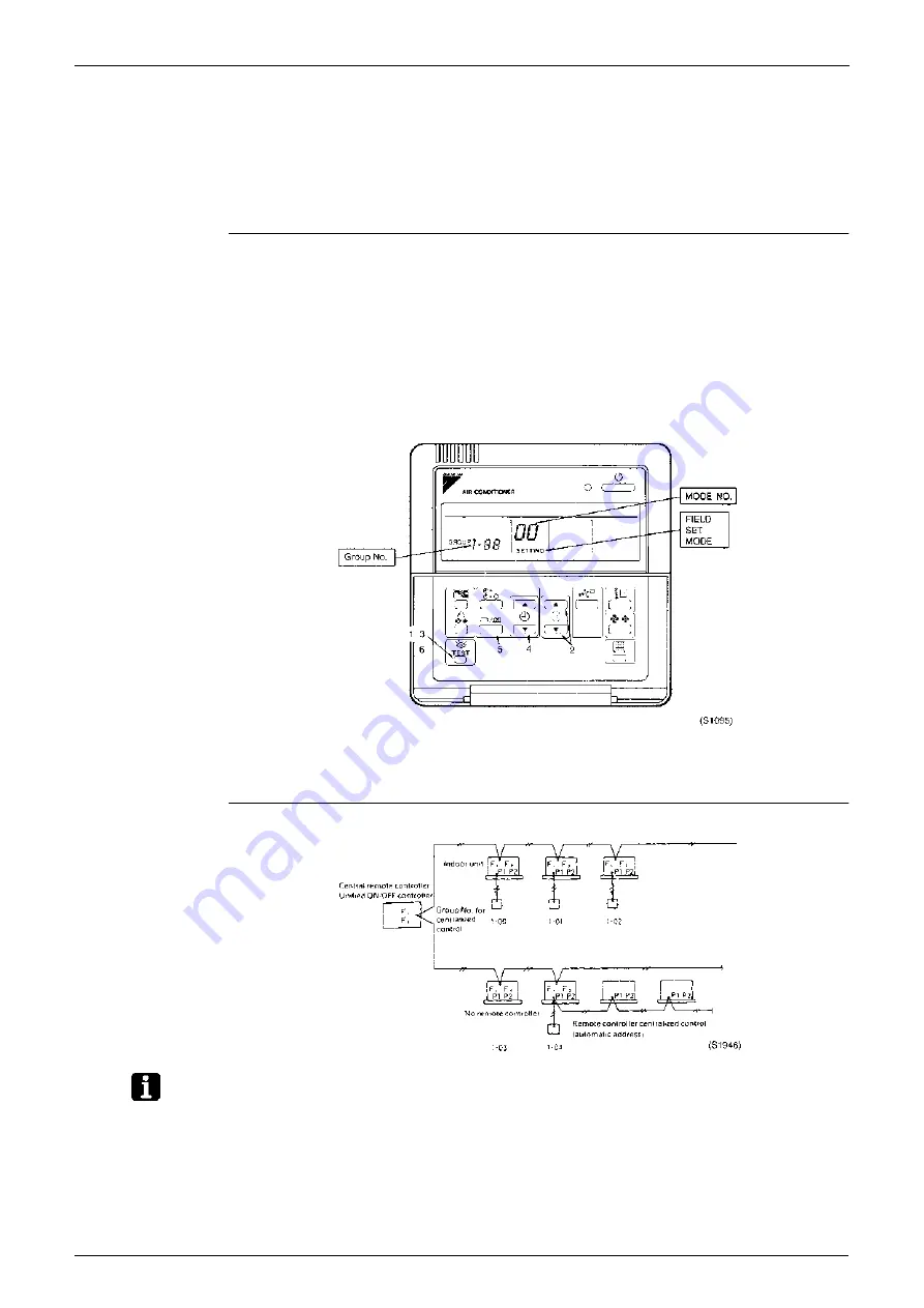
If carrying out centralized control with a central remote controller and unified ON/OFF
controller, you have to set the group No. for each group by remote controller.
To set the group No., first turn on the power supply of the central remote controller, unified
ON/OFF controller and indoor unit.
Centralized
Group No. Setting
by Remote
Controller
1. If the inspection/test button is pushed for 4 seconds or more when in the normal mode,
operation enters the “field set mode.”
2. Using the temperature control buttons, set the mode No. to “00.”
3. Push the inspection/test button to inspect the group No. display.
4. Using the programming time button, set the group No. for each group. (Group No. rises in
the order of 1-00, 1-01, ...1-15, 2-00 ...4-15, etc. The unified ON/OFF controller however
displays only the range of group numbers selected by the switch for setting each address.)
5. Push the timer ON/OFF button and enter the selected group No.
6. Push the inspection/test button and return to the normal mode.
∗
If the address has to be set individually for each unit for power consumption counting, etc., set
the mode No. to “30.”
Group No. Setting
Example
Note:
1. “F1,F2” indicates interface adaptor for SkyAir series.
2. If not using remote controllers, temporarily connect a remote controller to set the group No.,
set the group No. for centralized control, and then disconnect the controller.
Summary of Contents for D-Series
Page 1: ...Si18 525B Applied Models Super Multi Plus Cooling only Super Multi Plus Heat Pump D Series ...
Page 33: ...List of Functions Si18 525B 20 List of Functions ...
Page 71: ...Specifications Si18 525B 58 Specifications ...
Page 117: ...Refrigerant Flow for Each Operation Mode Si18 525B 104 Refrigerant Circuit ...
Page 171: ...Indoor Unit SkyAir Models Si18 525B 158 Function ...
Page 207: ...Test Operation and Field Setting for RA Indoor Unit Si18 525B 194 Test Operation ...
Page 336: ...Si18 525B Service Check Function Troubleshooting 323 ...
Page 469: ...Wiring Diagrams Si18 525B 456 Appendix ...
Page 475: ...Si18 525B vi Index ...


