Instruction
Si18-525B
284
Operation Manual
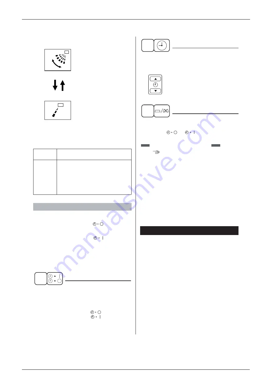
Press the AIR FLOW DIRECTION ADJUST
button to select the air direction as following.
The AIR FLOW FLAP display
swings as shown left and the
air flow direction continuously
varies. (Automatic swing set-
ting)
Press AIR FLOW DIRECTION
ADJUST button to select the air
direction of your choice.
The AIR FLOW FLAP display
stops swinging and the air
flow direction is fixed (Fixed
air flow direction setting).
MOVEMENT OF THE AIR FLOW FLAP
For the following conditions, micro computer con-
trols the air flow direction so it may be different from
the display.
Operation mode includes automatic operation.
Operate in the following order.
• The timer is operated in the following two ways.
• Programming the stop time (
) .... The sys-
tem stops
operating after the set time has elapsed.
• Programming the start time (
) .... The sys-
tem starts
operating after the set time has elapsed.
• The timer can be programmed a maximum of 72
hours.
• The start and the stop time can be simulta-
neously programmed.
Press the TIMER MODE START/STOP but-
ton several times and select the mode on
the display.
The display flashes.
For setting the timer stop .... “
”
For setting the timer start .... “
”
Press the PROGRAMMING TIME button and
set the time for stopping or starting the sys-
tem.
When this button is pressed, the time
advances by 1 hour.
When this button is pressed, the time
goes backward by 1 hour.
Press the TIMER ON/OFF button.
The timer setting procedure ends.
The display “
or
” changes from flash-
ing light to a constant light.
NOTE
• When setting the timer Off and On at the same
time, repeat the above procedure from 1 to 3
once again.
When the timer is programmed to stop the system
after 3 hours and start the system after 4 hours, the
system will stop after 3 hours and then 1 hour later
the system will start.
• After the timer is programmed, the display shows
the remaining time.
• Press the TIMER ON/OFF button once again to
cancel programming. The display vanishes.
Observe the following precautions to ensure the
system operates.
• Adjust the room temperature properly for a com-
fortable environment. Avoid excessive heating or
cooling.
• Prevent direct sunlight from entering a room dur-
ing cooling operation by using curtains or blinds.
• Ventilate the room regularly.
Using the unit for long periods of time requires
attentive ventilation of the room.
• Do not place items that might be damaged by
water under the indoor unit.
Water may condensate and drip if the humidity
reaches 80% or if the drain exit gets clogged.
• Keep doors and windows closed. If the doors and
windows remain open, room air will flow out and
cause to decrease the effect of cooling and heat-
ing.
Operation
mode
Heating
Operation
condition
• When starting operation
• When room temperature is higher
than the set temperature
• At defrost operation
(Air is blown horizontally to prevent
the cool air from being blown
directly onto anyone in the room.)
PROGRAM TIMER OPERATION
swing
TIMER MODE START/STOP
1
7. OPTIMUM OPERATION
PROGRAMMING TIME
2
TIMER ON/OFF
3
Refer to figure 4 on page
[1]
Summary of Contents for D-Series
Page 1: ...Si18 525B Applied Models Super Multi Plus Cooling only Super Multi Plus Heat Pump D Series ...
Page 33: ...List of Functions Si18 525B 20 List of Functions ...
Page 71: ...Specifications Si18 525B 58 Specifications ...
Page 117: ...Refrigerant Flow for Each Operation Mode Si18 525B 104 Refrigerant Circuit ...
Page 171: ...Indoor Unit SkyAir Models Si18 525B 158 Function ...
Page 207: ...Test Operation and Field Setting for RA Indoor Unit Si18 525B 194 Test Operation ...
Page 336: ...Si18 525B Service Check Function Troubleshooting 323 ...
Page 469: ...Wiring Diagrams Si18 525B 456 Appendix ...
Page 475: ...Si18 525B vi Index ...


