Si18-525B
Instruction
Operation Manual
293
Refer to figure 1 on page [1]
The illustrations in this operating manual corre-
spond to the remote control format BRC1C type.
Although the display and shape of the buttons on
the BRC1B type are slightly different, they may be
operated in the same manner.
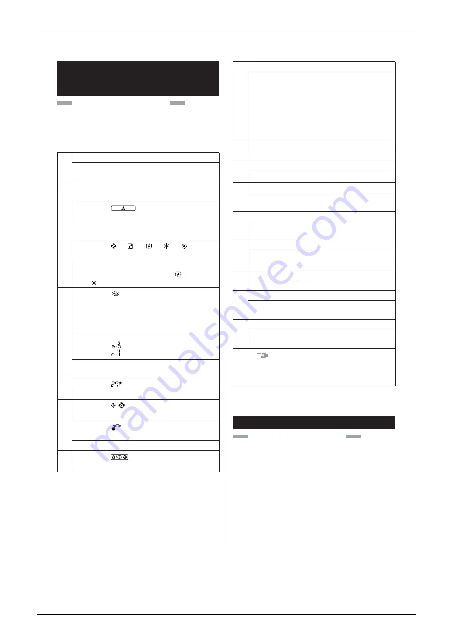
5. NAME AND FUNCTION OF EACH
SWITCH AND DISPLAY ON THE
REMOTE CONTROLLER
1
ON/OFF BUTTON
Press the button and the system will start. Press
the button again and the system will stop.
2
OPERATION LAMP (RED)
The lamp lights up during operation.
3
DISPLAY “
” (UNDER CENTRAL-
IZED CONTROL)
When this display shows, the system is
UNDER CENTRALIZED CONTROL.
4
DISPLAY “
” “
” “
” “
” “
”
(OPERATION MODE)
This display shows the current OPERATION
MODE. For cooling only type, “
” (Auto)
and “
” (Heating) are not installed.
5
DISPLAY “
TEST
” (INSPECTION/TEST
OPERATION)
When the INSPECTION/TEST OPERATION
BUTTON is pressed, the display shows the
system mode is in.
6
DISPLAY “
” (PROGRAMMED TIME)
This display shows the PROGRAMMED
TIME of the system start or stop.
7
DISPLAY “
” (SET TEMPERATURE)
This display shows the set temperature.
8
DISPLAY “
” (FAN SPEED)
This display shows the set fan speed.
9
DISPLAY “
” (TIME TO CLEAN AIR FIL-
TER)
Refer to “HOW TO CLEAN THE AIR FILTER”.
10
DISPLAY “
” (DEFROST)
Refer to “DEFROST OPERATION”.
hr
hr
C
Refer to figure 1 on page [1]
• Operating procedure varies with heat pump type
and cooling only type. Contact your Daikin dealer
to confirm your system type.
• To protect the unit, turn on the main power switch
6 hours before operation.
• If the main power supply is turned off during oper-
ation, operation will restart automatically after the
power turns back on again.
11
NON-FUNCTIONING DISPLAY
If that particular function is not available,
pressing the button may display the words
“NOT AVAILABLE” for a few seconds.
When running multiple units simultaneously
The “NOT AVAILABLE” message will only be
appear if none of the indoor units is equipped
with the function. If even one unit is equipped
with the function, the display will not appear.
12
TIMER MODE START/STOP BUTTON
Refer to “PROGRAM TIMER OPERATION”.
13
TIMER ON/OFF BUTTON
Refer to “PROGRAM TIMER OPERATION”.
14
INSPECTION/TEST OPERATION BUTTON
This button is used only by qualified service
persons for maintenance purposes.
15
PROGRAMMING TIME BUTTON
Use this button for programming “START and/
or STOP” time.
16
TEMPERATURE SETTING BUTTON
Use this button for SETTING TEMPERA-
TURE.
17
FILTER SIGN RESET BUTTON
Refer to “HOW TO CLEAN THE AIR FILTER”.
18
FAN SPEED CONTROL BUTTON
Press this button to select the fan speed,
HIGH or LOW, of your choice.
19
OPERATION MODE SELECTOR BUTTON
Press this button to select OPERATION
MODE.
NOTE
• For the sake of explanation, all indications are
shown on the display in figure 1 contrary to
actual running situations.
6. OPERATION PROCEDURE
Summary of Contents for D-Series
Page 1: ...Si18 525B Applied Models Super Multi Plus Cooling only Super Multi Plus Heat Pump D Series ...
Page 33: ...List of Functions Si18 525B 20 List of Functions ...
Page 71: ...Specifications Si18 525B 58 Specifications ...
Page 117: ...Refrigerant Flow for Each Operation Mode Si18 525B 104 Refrigerant Circuit ...
Page 171: ...Indoor Unit SkyAir Models Si18 525B 158 Function ...
Page 207: ...Test Operation and Field Setting for RA Indoor Unit Si18 525B 194 Test Operation ...
Page 336: ...Si18 525B Service Check Function Troubleshooting 323 ...
Page 469: ...Wiring Diagrams Si18 525B 456 Appendix ...
Page 475: ...Si18 525B vi Index ...


