Si18-525B
Specifications
Specifications
27
50Hz 220-230V / 60Hz 220-230V
Note:
1. BP or Indoor Unit Max. Height - BP or Indoor Unit Min. Height
→
Max. 15m.
Set up BP and indoor unit within 15m height difference.
2. The piping connection must be cut so as to suit the piping sizes of the indoor unit which will be connected.
The same sizes should be used for the piping on the outdoor unit.
3. ( )* : including auxiliary piping length
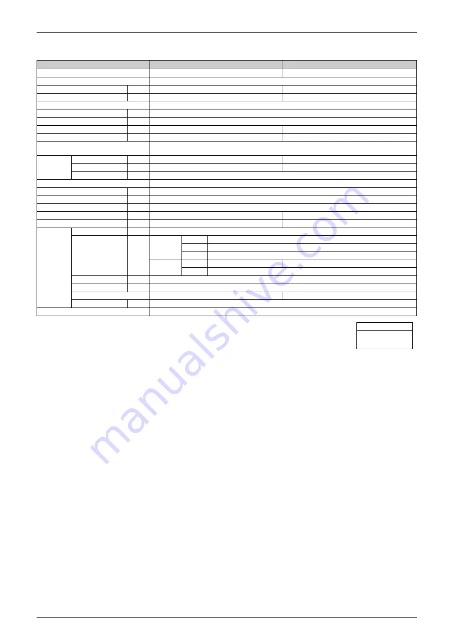
Model
BPMKD967A2
BPMKD967A3
Connectable Indoor Units
1~2 Units
1~3 Units
Casing Color
Paintingless
Power Consumption
W
10
10
Running Current
A
0.05
0.05
Refrigerant Type
R22
Dimension (H×W×D)
mm
180×294(650)*×350
Package Dimension (H×W×D)
mm
257×738×427
Machine Weight
kg
7.5
8
Gross Weight
kg
11
12
Number of Wiring Connections
3 for Power Supply (Including Earth Wiring), 2 for Interunit Wiring (Outdoor Unit-BP, BP-BP)
4 for Interunit Wiring (BP-Indoor Unit)
Piping
Connection
(Brazing)
Liquid
mm
Main :
φ
9.5×1 / Branch :
φ
6.4×2
Main :
φ
9.5×1 / Branch :
φ
6.4×3
Gas
mm
Main :
φ
19.1×1 / Branch :
φ
15.9×2
Main :
φ
19.1×1 / Branch :
φ
15.9×3
Drain
mm
Drain Processingless
Heat Insulation
Both Liquid and Gas Pipes
Max. Piping Length
m
—
Amount of Additional Charge
g/m
—
Max. Height Difference
m
—
Max. Combination
kW
14.2
20.8
Min. Combination
kW
2.5
2.5
Accessories
Installation Manual
pc.
1
L Shape Reducer
pc.
For Main
Liquid
1 (O.D.
φ
9.5 to I.D.
φ
6.4)
Gas
1 (O.D.
φ
15.9 to I.D.
φ
12.7)
Gas
1 (O.D.
φ
19.1 to I.D.
φ
15.9, 19.1)
For Branch
Gas
2 (O.D.
φ
15.9 to I.D.
φ
12.7, 9.5)
3 (O.D.
φ
15.9 to I.D.
φ
12.7, 9.5)
Liquid
1 (O.D.
φ
6.4 to I.D.
φ
9.5)
Hanger Metal
pc.
4
Screws
pc.
8 (M4×8)
Heat Insulation (2pc. is 1 set)
3 Set
4 Set
Binding Band
pc.
2
Drawing No.
4D050451A
Conversion Formulae
kcal/h=kW×860
Btu/h=kW×3414
cfm=m³/min×35.3
Summary of Contents for D-Series
Page 1: ...Si18 525B Applied Models Super Multi Plus Cooling only Super Multi Plus Heat Pump D Series ...
Page 33: ...List of Functions Si18 525B 20 List of Functions ...
Page 71: ...Specifications Si18 525B 58 Specifications ...
Page 117: ...Refrigerant Flow for Each Operation Mode Si18 525B 104 Refrigerant Circuit ...
Page 171: ...Indoor Unit SkyAir Models Si18 525B 158 Function ...
Page 207: ...Test Operation and Field Setting for RA Indoor Unit Si18 525B 194 Test Operation ...
Page 336: ...Si18 525B Service Check Function Troubleshooting 323 ...
Page 469: ...Wiring Diagrams Si18 525B 456 Appendix ...
Page 475: ...Si18 525B vi Index ...


