Outdoor Unit
Si18-525B
412
Removal Procedure
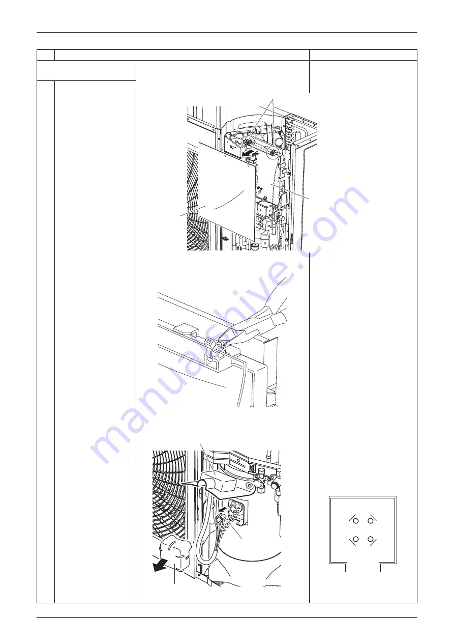
3. Removing the power filter
PCB.
1
Cut off the 2 top clamps
and remove the drip
proof cover.
Cut off with nippers.
The clamp is to be kept in stock.
2
Tilt up the compressor's
sound proof cover.
Using long nose pliers, pull out
the following.
U: Red
V: White
W: Blue
N: Brown
3
Remove the terminal
cover.
4
Disconnect the
compressor lead
connector (terminal).
Step
Procedure
Points
Clamps
Power filter PCB
Drip proof cover
(Q0527)
(Q0471)
Sound proof cover
Terminal
Terminal cover
(Q0473)
N
W
U
V
Summary of Contents for D-Series
Page 1: ...Si18 525B Applied Models Super Multi Plus Cooling only Super Multi Plus Heat Pump D Series ...
Page 33: ...List of Functions Si18 525B 20 List of Functions ...
Page 71: ...Specifications Si18 525B 58 Specifications ...
Page 117: ...Refrigerant Flow for Each Operation Mode Si18 525B 104 Refrigerant Circuit ...
Page 171: ...Indoor Unit SkyAir Models Si18 525B 158 Function ...
Page 207: ...Test Operation and Field Setting for RA Indoor Unit Si18 525B 194 Test Operation ...
Page 336: ...Si18 525B Service Check Function Troubleshooting 323 ...
Page 469: ...Wiring Diagrams Si18 525B 456 Appendix ...
Page 475: ...Si18 525B vi Index ...


