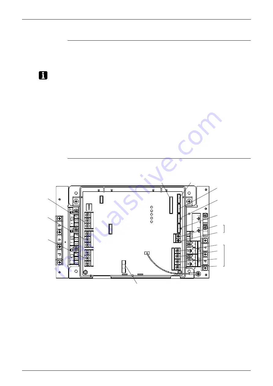
Printed Circuit Board Connector Wiring Diagram
Si18-525B
66
Printed Circuit Board Connector Wiring Diagram
1.2
Branch Provider Unit
Connectors
Note:
Other Designations
X23A and X5M are not used for BPMKS967A2(B) and BPMKD967A2.
PCB Detail
1)
X20A
Connector for Bypass Electronic Expansion Valve
2)
X21A to X23A
Connector for Electronic Expansion Valve to Room A, B and C
3)
X90A
Connector for Thermistors
1)
F2U
Fuse (AC250V 3.15A)
2)
X3M
Terminal for Inter Connecting Wire to Room A
3)
X4M
Terminal for Inter Connecting Wire to Room B
4)
X5M
Terminal for Inter Connecting Wire to Room C
5)
F1
,
F2
(on X6M)
Terminal for Transmission to Outdoor Unit or Other BP units
6)
L1
,
N1
(on X1M)
Terminal for Power Supply
7)
L2
,
N2
(on X1M)
Terminal for Power Supply to other BP units
8)
H1P
(LED A)
LED for Service Monitor
9)
H2P~H5P
(LED 1 to 4) LED for Fault Indication
X3M
X4M
X5M
F2U
3P152439
X22A
X21A
X20A
F2
X6M
X1M
F1
N2
L2
N1
L1
X90A
X23A
H1P (LED A)
H2P (LED 1)
H3P (LED 2)
H4P (LED 3)
H5P (LED 4)
N2
L2
N1
L1
Summary of Contents for D-Series
Page 1: ...Si18 525B Applied Models Super Multi Plus Cooling only Super Multi Plus Heat Pump D Series ...
Page 33: ...List of Functions Si18 525B 20 List of Functions ...
Page 71: ...Specifications Si18 525B 58 Specifications ...
Page 117: ...Refrigerant Flow for Each Operation Mode Si18 525B 104 Refrigerant Circuit ...
Page 171: ...Indoor Unit SkyAir Models Si18 525B 158 Function ...
Page 207: ...Test Operation and Field Setting for RA Indoor Unit Si18 525B 194 Test Operation ...
Page 336: ...Si18 525B Service Check Function Troubleshooting 323 ...
Page 469: ...Wiring Diagrams Si18 525B 456 Appendix ...
Page 475: ...Si18 525B vi Index ...


