Si18-525B
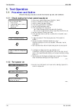
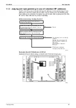
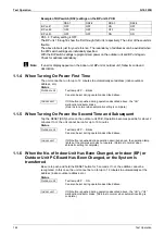
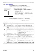
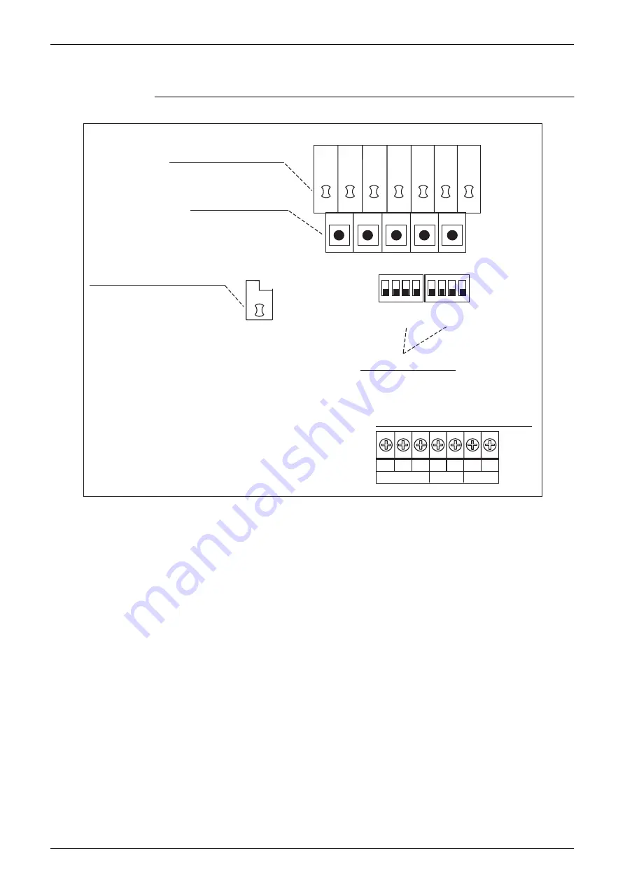
Outdoor Unit PCB Layout
Test Operation
165
2.
Outdoor Unit PCB Layout
Outdoor Unit PCB
BS1
MODE
SET
RETURN
TEST
RESET
BS2
BS3
BS4
BS5
H1P H2P H3P H4P H5P H6P H7P
1 2 3 4
1 2 3 4
A
B
C
C/H SELECTOR TO BP UNIT
(2) Set mode display (LED)
(3) Mode setting switch
(1) Microcomputer normal monitor
(4)Local setting switch
Connection terminal for transmission use
DS1
DS2
HAP
(Q0404)
(1) Microcomputer normal monitor (LED Green)
This monitor blinks while in normal operation, and turns on or off when a malfunction occurs.
(2) Set mode display (LED Orange)
LEDs display mode according to the setting.
(3) Mode setting switch
Used to change mode.
(4) Local setting switch
Used to make local settings.
F1 F2 F1 F2
Summary of Contents for D-Series
Page 1: ...Si18 525B Applied Models Super Multi Plus Cooling only Super Multi Plus Heat Pump D Series ...
Page 33: ...List of Functions Si18 525B 20 List of Functions ...
Page 71: ...Specifications Si18 525B 58 Specifications ...
Page 117: ...Refrigerant Flow for Each Operation Mode Si18 525B 104 Refrigerant Circuit ...
Page 171: ...Indoor Unit SkyAir Models Si18 525B 158 Function ...
Page 207: ...Test Operation and Field Setting for RA Indoor Unit Si18 525B 194 Test Operation ...
Page 336: ...Si18 525B Service Check Function Troubleshooting 323 ...
Page 469: ...Wiring Diagrams Si18 525B 456 Appendix ...
Page 475: ...Si18 525B vi Index ...


