Si18-525B
Troubleshooting for RA Indoor Unit
Troubleshooting
339
4.6.4
Power Supply Waveforms Check
Check No.10
Measure the power supply waveform between pins 1 and 3 on the terminal board, and check
the waveform disturbance.
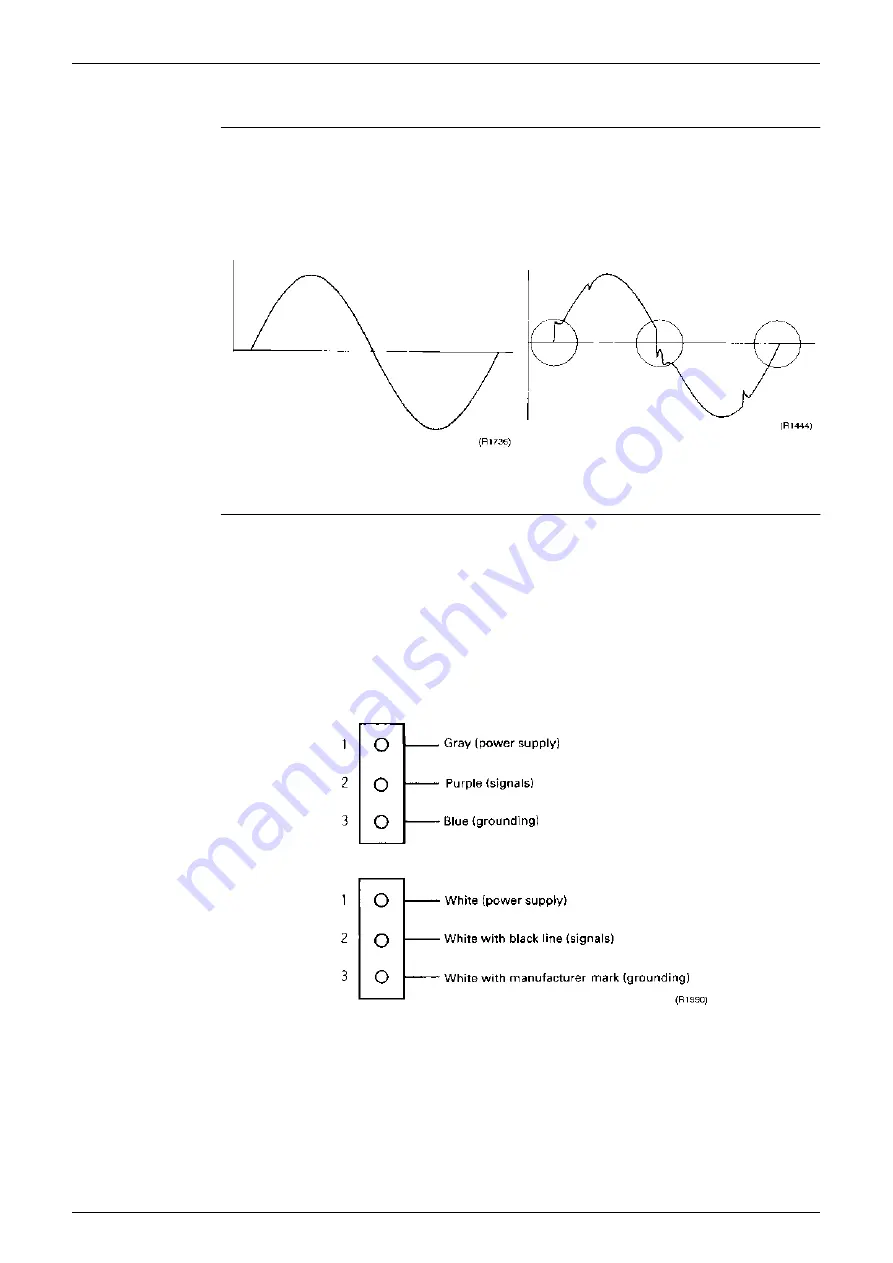
Check to see if the power supply waveform is a sine wave (Fig.1).
Check to see if there is waveform disturbance near the zero cross (sections circled in Fig.2)
4.6.5 Hall IC Check
Check No.16
1. Check the connector connection.
2. With the power ON, operation OFF, and the connector connected, check the following.
∗
Output voltage of about 5 V between pins 1 and 3.
∗
Generation of 3 pulses between pins 2 and 3 when the fan motor is operating.
Failure of (1) faulty PCB Replace the PCB.
Failure of (2) faulty Hall IC Replace the fan motor.
Both (1) and (2) result Replace the PCB.
The connector has 3 pins, and there are two patterns of lead wire colors.
[Fig.1]
[Fig.2]
Summary of Contents for D-Series
Page 1: ...Si18 525B Applied Models Super Multi Plus Cooling only Super Multi Plus Heat Pump D Series ...
Page 33: ...List of Functions Si18 525B 20 List of Functions ...
Page 71: ...Specifications Si18 525B 58 Specifications ...
Page 117: ...Refrigerant Flow for Each Operation Mode Si18 525B 104 Refrigerant Circuit ...
Page 171: ...Indoor Unit SkyAir Models Si18 525B 158 Function ...
Page 207: ...Test Operation and Field Setting for RA Indoor Unit Si18 525B 194 Test Operation ...
Page 336: ...Si18 525B Service Check Function Troubleshooting 323 ...
Page 469: ...Wiring Diagrams Si18 525B 456 Appendix ...
Page 475: ...Si18 525B vi Index ...


