background image

D2CND0 D2CND0 D2TND0 

D2TND0 D2TND024A4AA 

Wall-mounted condensing boiler

ESIE17-09 / 2017.11

Servicing manual

20

4.8 

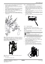
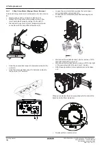
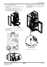
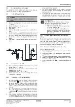
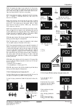
Syphon Part Removal

• 

Isolate the appliance from powersupply and closedown 

the gas valve.

• 

Drain the water from the boiler (refer to Section 4.1).

• 

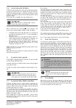
Remove the condensate syphon hose’s drain pipe (refer 

to Section 4.1)

• 

Remove the syphon part  that  by holding body part (1,2) .

• 

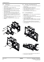
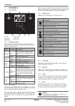
Isolate the appliance from power  and closedown the gas 

valve.

• 

Drain the water from the boiler (refer to Section 4.1 )

• 

Open the appliance ( refer to Section 4.2)

• 

Take out the silencer (refer to Section 4.4).

• 

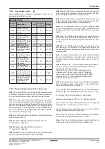
Remove the syphon part from condensate sump by turn

-

ing counter clockwise (refer to Section 4.8).

• 

Remove the condensate sump from the heat exchanger 

(refer to section 4.4).

• 

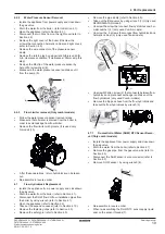
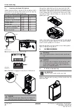
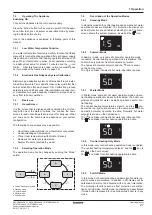
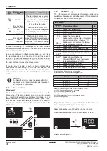
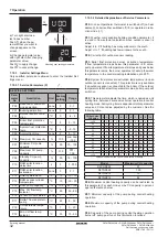
Undo the screw between flow hydroblock and plate heat 

exchanger (1).

• 

Undo the screw that between return group and plate heat 

exchanger (1).

4.9 

Plate  Heat  Exchanger  Removal  (Only  combi 


models)

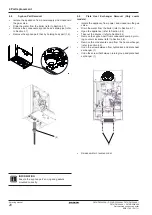
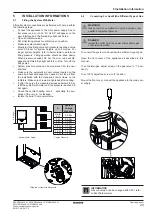
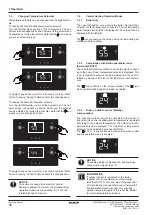
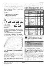
Ensure the  syphon part’s o-ring and gaskets 

mounted correctly.

INFORMATION

4 Part replacement

(1)

(2)

• 

Re-assemble in reverse order.

(1)

Summary of Contents for D2CND024A1AA

Page 1: ...Servicing manual Wall mounted condensing boiler D2CND024A1AA D2CND024A4AA D2TND012A4AA D2TND018A4AA D2TND024A4AA English Servicing manual Wall mounted condensing boiler...

Page 2: ...CND024A1AA D2CND024A4AA D2TND012A4AA D2TND018A4AA D2TND024A4AA Wall mounted condensing boiler ESIE17 09 2017 11 Servicing manual 2 LOG Version Code Description Date ESIE17 09 Document release 1 11 201...

Page 3: ...s 26 7 1 2 LCD screen 26 7 1 3 Status icons 26 7 1 4 Daikin Eye 26 7 1 5 Stand by 26 7 1 6 Flame 26 7 1 7 Error 26 7 2 Operating The Appliance 27 7 2 1 Low Water Temperature Function 27 7 2 2 Electron...

Page 4: ...s composed of an LCD screen push buttons and two dials and which is located on the front cover of the appliance The appliance is equipped with several safety systems to pro tect it against dangerous c...

Page 5: ...w temperature sensor which is located at the outlet of the main heat exchanger This protection ac tivates the boiler pump when the water temperature drops below depends on P03 parameter value and it a...

Page 6: ...ostat 17 Fan 18 Return temperature sensor 19 Silencer 20 Automatic air vent pump 21 Water pressure sensor 22 By pass 23 Boiler pump 24 Domestic hot water flow sensor 25 Domestic hot water flow limiter...

Page 7: ...56 68 56 77 Combustion products temperature min max G31 C 56 60 56 68 55 76 Maximum combustion products temp at nominal heat input C 80 82 90 CO2 Emission at nominal and minimum heat input G20 9 0 0...

Page 8: ...14_FLOW X4 15_OWC X4 16_OWC X3 1_PwmWh X3 2_PwmB1 X3 3_ReWhSw X3 4_Gnd X3 5_5v X2 8_LP1 X2 1_SOLs X2 2_SOL X2 3_RTs X2 4_RT X2 5_NPSRT X2 6_LPSRT X2 7_NP1 X5 X4 X3 X2 X1 X1 1_NP X1 2_LP X1 3_NI X1 4_...

Page 9: ...stable spanner Number 30 32 24 26 14 18 3 3 Spare parts To ensure long lasting operation of the appliance always use original spare parts Spare parts must be ordered from spare parts catalog by specif...

Page 10: ...Domestic Hot Water Circuit Isolate the appliance from power supply and closedown the gas valve Close all the isolating valves on the central heating circuit Open the drain valve 1 and drain the centr...

Page 11: ...from power supply and closedown the gas valve Undo M5 screw at the figure 1 Remove the assembly clips of front cover 2 Remove the front cover by pulling up 3 Undo 2 sheet screw holding control panel 4...

Page 12: ...connector of flow sensor 2 and pressure sensor 3 Disconnect the wire connector of 3 way valve refer to 4 6 1 Dismantle the ignition electrode and earth cable from the power supply 4 Firstly loosen th...

Page 13: ...socket s housing and disconnect the sensor 13 Take out cable connections of fan manually 14 Re assemble in reverse order Be careful all electrical cables during the removal of cable group wire harnes...

Page 14: ...e gas supply pipe from the gas valve and brass nipple by using wrench 1 Unscrew the 2xM5 screws that connect gas manifold and burner hood 2 Seperate the gas manifold from the burner hood clip and take...

Page 15: ...low return and flue NTC sensors and high limit thermostat refer to Section 4 3 Take out the syphon parts refer to Section 4 8 Unscrew the screws that connect hermetic cabinet and right cover 1 Remove...

Page 16: ...nted condensing boiler ESIE17 09 2017 11 Servicing manual 16 4 Part replacement Remove the screw holding the hermetic cabinet with main heat exchanger M5 allen 9 Detach the main heat exchanger by push...

Page 17: ...nti nel s products which are appropriate for cleaning of heat exchanger inside Inspect the heat exchanger from the top and bottom Take any foreign object Use the cleaning tool into the heat exchanger...

Page 18: ...2 Undo the screws that connect to hermetic cabinet to the pump 3 Undo the 2 screws that connect to hermetic cabinet to the pump 4 for T models Loosen the union joint that provides the return pipe pump...

Page 19: ...the DHW flow CH flow installation pipes from the boiler by using wrench refer to Section 4 1 Open the appliance refer to Section 4 2 Take out the expansion vessel refer to Section 4 10 Remove the fast...

Page 20: ...osedown the gas valve Drain the water from the boiler refer to Section 4 1 Open the appliance refer to Section 4 2 Take out the silencer refer to Section 4 4 Remove the syphon part from condensate sum...

Page 21: ...efer to Section 4 2 Remove the left cover of the boiler unscrew the screws that connects hermetic cabin and left cover 1 Undo the screws which connect expansion vessel and flow hydroblock 2 Disconnect...

Page 22: ...support s 3 screws holding the main pcb and remove the cable support 4 Unscrew the 3 screws that connect PCB and control panel 5 Isolate the appliance from power supply and closedown the gas valve Ope...

Page 23: ...pump and heat exchanger are opened Vent the air from the installation with the manual air vent screws on the radiators Make sure screws are tightened after venting If after the purge the pressure dec...

Page 24: ...w you can see the Cable glands placement Holes on the bottom sheet that are reserved for cable glands are covered with insulation material The insulation material must be bored if glands are to be use...

Page 25: ...fter first power ON the boiler does not increase its capacity above a preset value for about 12 minutes even if there is demand First 0 2 minutes The electronic gas adapti ve system calibrates itself...

Page 26: ...ashes to its maximum then constantly keeps glowing during burner operation with blue LED 7 1 7 Error The Daikin eye will go into error mode when a warning lockout or blocking error occurs During the e...

Page 27: ...re at stand by mode 7 3 2 Selecting Operation Mode The operation mode can be changed by pushing the Mode button 7 4 Description of the Operation Modes 7 4 1 Stand by Mode In stand by mode both central...

Page 28: ...o room ther mostat or outdoor sensor are connected The central heating water temperature setpoint is displayed The setpoint can be adjusted with the left dial The icon is shown on the screen when cent...

Page 29: ...Note Independent of personal use pattern Comfort mode preheating function could be adjusted to operate continuously from the user settings For example When the domestic hot water DHW mode is activate...

Page 30: ...ximum value during domestic hot water operation 100 c A10 0 Standby mode burner is not active A10 1 Start up preparation to ignition A10 2 Ignition and flame stabilisition phase A10 3 Release control...

Page 31: ...onnected this parameter value is the central heating water tempearture setpoint when there is no a heat demand Note For this parameter value to be active Reducing mode have to be enabled by your servi...

Page 32: ...0 20 P19 Min CH flow temp setpoint C 30 10 30 P00 In case Opentherm thermostat is switched off no heat demand boiler is either switched off 0 or operates in redu ction mode 1 P01 Weather compensation...

Page 33: ...ble only for storage tank type models P15 Max temperature that can be adjusted by left dial when setting central heating flow temperature P16 This parameter is a read only parameter which shows the co...

Page 34: ...0 C 10 circuits and lenght of the each circuit is 80 metres without an additional pump When the boiler is connected to an UFH system the following parameter changes must certainly be done Parameter Ma...

Page 35: ...ir ratio will be far from average value which may also result in ignition problems delayed or loud ignition If such problems are present C02 parameter must be optimized first If C02 parameter change i...

Page 36: ...may cause loud ignition C03 This parameter is used to increase maximum allowable flue duct length by increasing fan speed Adjust this parameter to 3 to use longer flue ducts for C13x and C33x types of...

Page 37: ...e pass word as 043 c For 100 calibration and C12 C13 adjustment set the password as 046 Press Enter button The boiler will start calibration ac cording to above mentioned input values LED s on the scr...

Page 38: ...set to 45 C 2 Pump runs at 100 capacity Function is active for 10 minutes of burner operation After function is ended boiler operates according to central heating setpoint adjusted by the customer an...

Page 39: ...mall plug which contains a programmed memory With BCC set of parameters inside the PCB can be changed at field without need to change the PCB itself The BCC con tains all control parameters and safety...

Page 40: ...or code will still be shown on display Resetting the boiler will remove the error 9 1 4 Error during Parameter transfer If an error occurs during the Parameter transfer or if parameter update is not i...

Page 41: ...12 66 Ion base val ue exceeds lower factory limit Reset the boiler Make a manuel calibration Check the ionization elecktrode it s cable connection and it s earth cable Replace if defective ER ROR CODE...

Page 42: ...leshooting ERROR CODE REASON ELIMINATION 81 01 Flow tem perature sensor fault Check continuity between the sen sor and PCB replace wire harness if necessary Check flue tempera ture sensor resistance u...

Page 43: ...the building should be checked and voltage stabiliser should be used for smooth operation U4 65 Opentherm RT connection is defective Boiler operates as if Opentherm room thermostat not connected Check...

Page 44: ...TMA S STEMLER SAN T C A K kbakkalk y Mah Kay da Cad No 1 Kat 21 22 34750 Ata ehir STANBUL T RK YE Tel 0216 453 27 00 Faks 0216 671 06 00 a r Merkezi 444 999 0 Web www daikin com tr ESIE17 09 2017 11 C...

Reviews: