D2CND0 D2CND0 D2TND0
D2TND0 D2TND024A4AA
Wall-mounted condensing boiler
ESIE17-09 / 2017.11
Servicing manual
39
8.3
Pump Control For By-pass Opeariton
At low pump capacities, by-pass valve opens but flow can not
reach sufficient rates so high-limit thermostat might block the
boiler. By increasing pump capacity at high operation tem
-
peratures, more by-pass flow is provided so Flow NTC pro
-
tection can stop the boiler before High limit thermostat. So
non-volatile lock-out is prevented.
Pump control for by-pass operation is active if;
CH flow set value ≥ 70 °C
or
Flow NTC value ≥ 75 °C
By this function, pump mininum capacity is set to 80% (50%
for normal opeation).
Note:
In case an outside sensor is connected , the room set
point is adjusted from CUI instead of CH flow set value. The
“CH flow Set value” will be calculated and will be used for
criteria above.
Note:
When burner is in operation and heat demand disap
-
pears (e.g. room thermostat opens) the pump capacity during
pump overrun-time, will be set to 50% (Standby-Pump-Ca
-
pacity CH) instead of 80% (min. Bypass-Pump-Capacity CH).
8.4
Supervision Flow/Return Temp. (Delta-T control)
This function protects the heat exchanger against termal
stresses and provides smooth operation.
Delta-T supervision has four steps;
1. If Delta-T exceeds 25°C, Pump capacity is increased to
100%.
2. Burner capacity is reduced step by step if 30°C < Delta-T
< 35°C
3. Burner operate at minimum capacity if 35°C < Delta-T
< 40°C
4. Burner stops and error code 8H-65 is generated. Burner
does not operate at least 150 seconds.
9.1
Boiler Chip Card (BCC)
BCC is a small plug, which contains a programmed memory.
With BCC, set of parameters inside the PCB can be changed
at field without need to change the PCB itself. The BCC con
-
tains all control parameters and safety parameters.
9.1.1
Spare Part PCB
PBC’s that will be used as spare part, all have 24 kW combi
boiler parameters originally. The replacement PCB’s have to
be used with suitable BCC’s at the field. Each model has a dif
-
ferent BCC since parameter values differ for different models.
Suitable BCC for each model can be found at models spare
part lists.
Suitable BCC must be used for related boiler model.
Otherwise, dangerous situations may occur. Suitable
BCC for each model can be found spare part list of
the product.
WARNING
9 Optional Parts
9
OPTIONAL PARTS
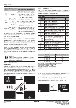
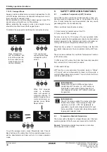
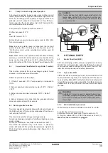
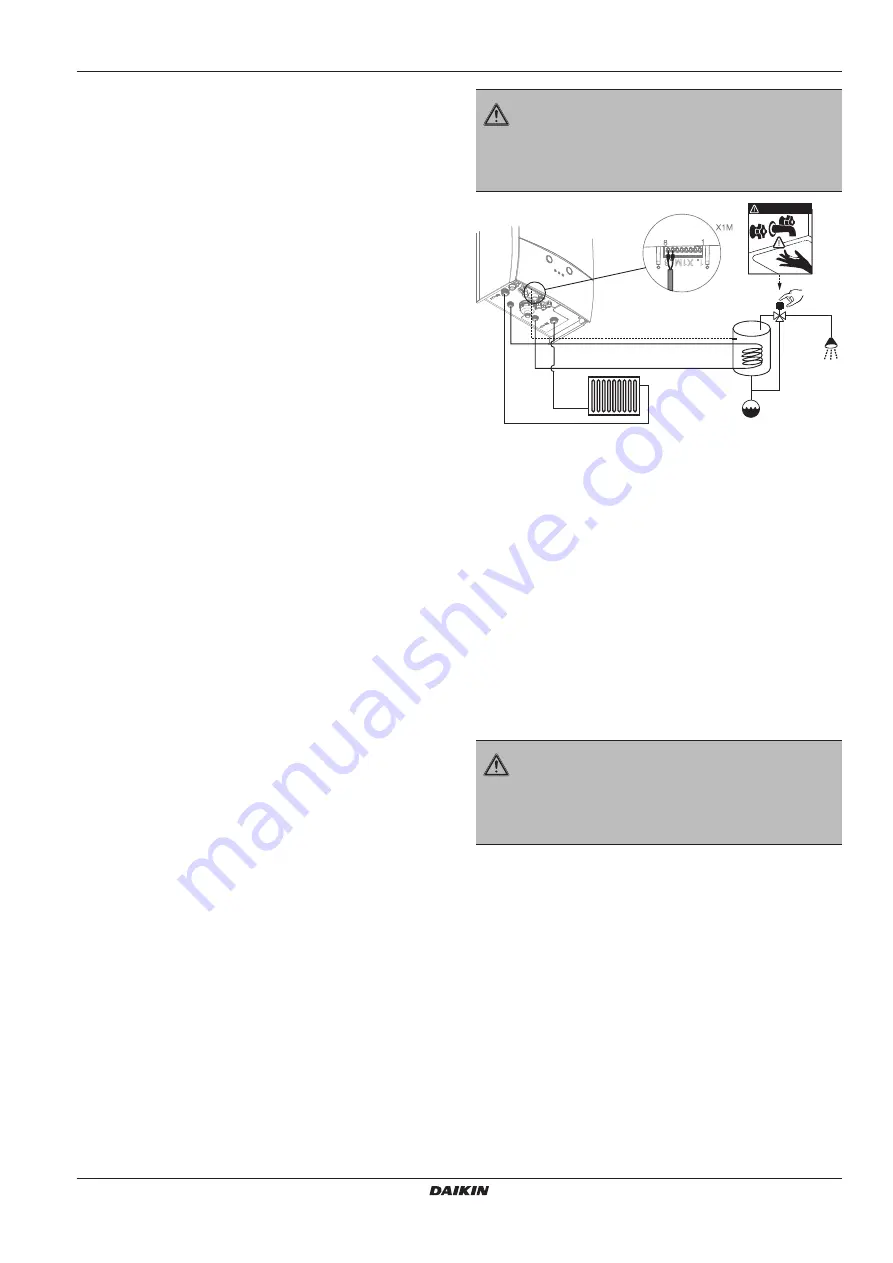
8.5 Anti-Legionella Function
To protect against legionnaire’s disease this function heats up
the DHW cylinder to 70oC and it is independent from the cur
-
rent set point for DHW.
This function is valid for storage tank type models.
Function is disabled in stand-by, full-off and heating only op
-
eration modes.
Function is disabled in case DHW is disabled from DOTT.
The function is activated every 7 x 24 hours = 1 week. Op
-
eration is finalized if the cylinder temperature is higher than
70oC. First Anti-Legionella-time-span after Power-On is 15
hours later.
>70°C
D A N G E R
< 60°C
If water is tapped just after the legionella function the
temperature will be 70oC and it may harm the cus
-
tomer. Thermostatic mixing valve use after the tank
is recommended.
DANGER
9.1.2
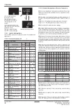
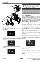
BCC installation procedure
Follow the steps below for installation of a BCC to a PCB;
1.
Isolate the unit from power mains.
2.
Remove the control panel cover (refer to section 4.11)
3.
Plug the related BCC to PCB X8 terminal as shown (1).
Make sure the correct BCC is plugged.

