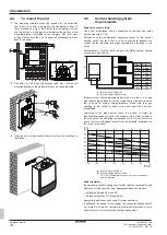
4 Installation
Installation Manual
13
D2CNL024A1AA
Wall-mounted condensing boiler
3P469346-12R – 2021.09
▪ Power supply cable must be equivalent to
H05RN-F (2451EC57)
as minimum requirement.
▪ The boiler is not approved to be operated at altitudes above 2000
meters above sea level.
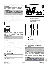
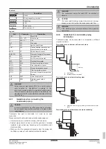
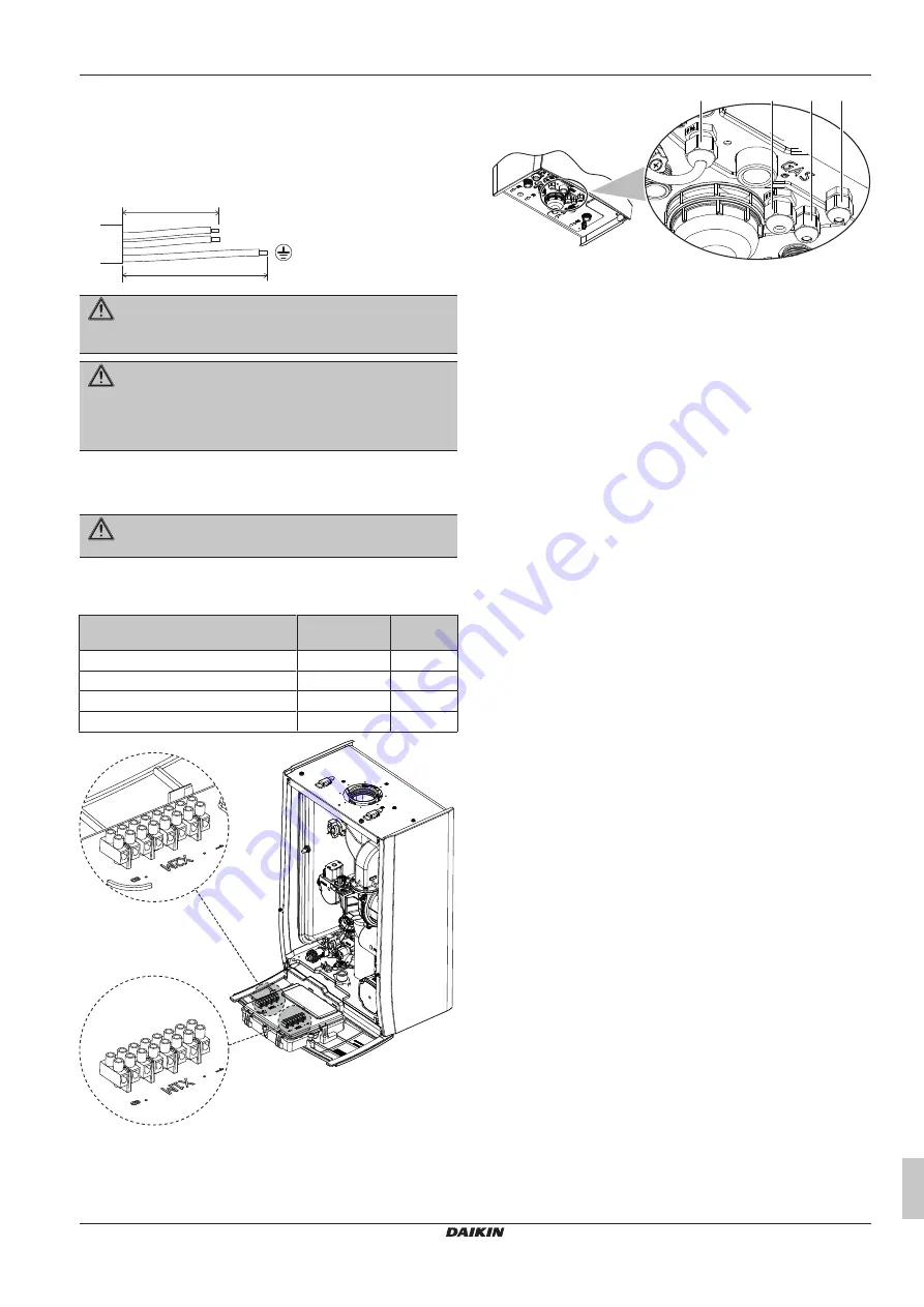
Observe the point mentioned below when wiring to the power supply
terminal board.
b
a
L
N
a<b
WARNING
Do NOT interchange the supply conductors L and the
neutral conductor N.
DANGER
Do not use gas and water pipes for earthing purposes and
ensure that they have not been used for this purpose
before. Failure to observe this relieves the manufacturer of
any responsibility.
4.8.5
Guidelines when connecting options to
the boiler
DANGER
X2M connector has 230 V AC.
Optional equipment is connected to the connectors, which are
located on the outside of the switch box. Do not open the switch box
to connect optional equipment.
Temperature control units
Connector
Connectio
n
Outdoor sensor
X1M
7-8
On-Off room thermostat
X1M
5-6
External power output (230 V AC)
X2M
3-4
Power cable (230 V AC)
X2M
1-2
X2M
1
8
X1M
1
8
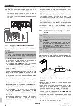
Wiring of the options that are to be connected to the internal
connectors must pop out from the inside of the unit via cable glands.
Cable glands that are sent with the unit must be assembled to the
bottom sheet of the boiler in case connection of these options.
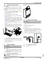
Below, you can see the cable glands placement.
PG 9
PG 9 PG 7 PG 7
Holes on the bottom sheet that are reserved for cable glands are
covered with insulation material. The insulation material must be
bored if glands are to be used.
Note:
Unit must be opened to mount cable glands. See
8] to reach the inside of the boiler.


