background image

3 About the unit

Installation Manual

5

D2CNL024A1AA
Wall-mounted condensing boiler
3P469346-12R – 2021.09

Pump  anti-blockage  system

:  The  pump  operates  for  30  seconds

every 24 hours during long periods of inactivity to ensure it does not
get stuck. To enable this function, the unit must be connected to the
power supply.

Three-way valve anti-blockage system

: In cases where the unit is

non-operational  for  prolonged  periods  of  time,  the  three-way  valve
switches its position every 24 hours to prevent it from getting stuck.
To  enable  this  function,  the  unit  must  be  connected  to  the  power
supply.

Safety  against  dry  operation

:  This  is  controlled  by  the  pressure

sensor.  It  turns  off  the  unit  and  ensures  system  safety  when  the
water pressure of the heating installation falls below 0.6 bar for any
reason.

Flame  ionisation  control

:  This  is  controlled  by  the  ionisation

electrode. It checks whether a flame forms on the burner surface or
not.  If  there  is  no  flame,  it  turns  the  unit  off  to  stop  gas  flow  and
warns the user.

High pressure protection

:

Pressure  sensor

:  When  heating  system  pressure  reaches

2.8  bar,  control  unit  stops  heating  operation  thus  preventing  the
pressure from rising.

Safety  valve

:  When  the  water  pressure  of  the  heating  circuit

exceeds  3  bar,  some  water  is  automatically  drained  from  the
safety valve to keep the pressure below 3 bar thus protecting the
boiler and heating installation.

Automatic  air  vents

:  There  are  two  air  vents;  one  on  the  pump,

other on the heat exchanger. They help discharging the air inside the
installation  and  heating  circuit  to  avoid  air  traps  and  consequent
operational problems.

Frost protection safety system

: This function protects the unit and

heating  installation  from  frost  damages.  It  is  controlled  by  the  flow
temperature  sensor,  which  is  located  at  the  outlet  of  the  main  heat
exchanger. This protection activates the boiler pump when the water
temperature drops below 15°C and it activates the burner when the
water temperature drops below 5°C. The unit keeps running until the
temperature reaches 15°C. To enable this function, the unit must be
connected to the power supply and its main gas valve must be open.
Any damage caused by frost is not covered by the warranty.

Low  voltage  safety  system

:  This  is  controlled  by  the  control  unit.

When the supply voltage drops below 170 V, the boiler goes to error
mode. It is a blocking error and the boiler will operate without reset
after  supply  voltage  is  above  180  V.  It  is  recommended  to  use  a
voltage regulator of suitable power and type in locations with voltage
fluctuations below this limit for faultless operation.

High  electric  supply  current  protection  system

:  A  fuse  on  the

control  unit  protects  equipment  and  wiring  against  the  damaging
effects  of  electrical  faults  which  is  caused  by  excess  currents,  and
disables  equipment  which  is  faulty.  The  fuse  "blows"  (opens)  when
the current carried exceeds the rated value for an excessive time.

Automatic  by-pass  system

:  This  ensures  that  the  flow  is  at  all

times  continued,  to  avoid  overheating  of  the  heat  exchanger.  This
system  is  also  supported  with  a  special  by-pass  function  in  the
control unit software.

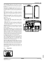
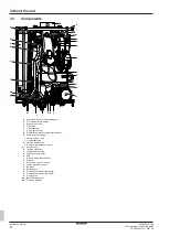
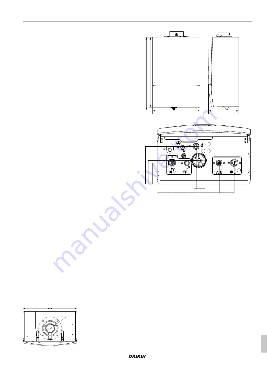
3.2

Dimensions

Top view

200

DN100

127

200

Front view and right side view

255.5

400

590

613.7

Bottom view

63

65

51

87

64.6

91.3

101.4

161.7

12.2

Summary of Contents for D2CNL-A1A

Page 1: ...Installation Manual Wall mounted condensing boiler English Installation Manual Wall mounted condensing boiler D2CNL024A1AA...

Page 2: ...e atitinka emiau nurodytus standartus ir arba kitus norminius dokumentus su s lyga kad yra naudojami pagal m s nurodymus tad ja lietoti atbilsto i ra ot ja nor d jumiem atbilst sekojo iem standartiem...

Page 3: ...re easy to separate and the plastics are marked This allows the various components to be sorted for appropriate recycling or disposal Units are marked with the following symbol This means that electri...

Page 4: ...thorised third parties Otherwise the unit warranty becomes void DANGER Isolate the boiler from the power mains before working on it WARNING Unit installation commissioning repair configuration and ser...

Page 5: ...heating circuit to avoid air traps and consequent operational problems Frost protection safety system This function protects the unit and heating installation from frost damages It is controlled by t...

Page 6: ...valve motor g Domestic hot water temperature sensor h Plate heat exchanger i Safety valve 3 bar j Condensate trap k Ignition transformer l Flue gas temperature sensor m Burner hood n Ignition electro...

Page 7: ...products temp at nominal heat input C 90 CO2 Emission at nominal and minimum heat input G20 8 7 9 3 0 2 NOx Class 6 Energy related products ErP specifications Symbol Unit D2CNL024A1AA Model D2CNL024 C...

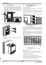
Page 8: ...ualified competent persons are allowed to open the unit Certain actions explained in this document such as gas conversion optional equipment connection require that the front cover is opened 1 Loosen...

Page 9: ...oom containing a bath or a shower then particular reference is drawn to the current I E E Wiring Regulations local Building Regulations or any other local regulations currently in service The intake a...

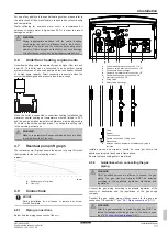
Page 10: ...d related system charge pressure are given below h p 6 m 0 8 bar 7 m 0 9 bar 8 m 1 0 bar 9 m 1 1 bar 10 m 1 2 bar 11 m 1 3 bar 12 m 1 4 bar 13 m 1 5 bar h h System water height m p System charge press...

Page 11: ...mp lift graph The residual pump lift graph shows the amount of pump lift mbar that remains for the central heating circuit 0 0 0 0 100 200 300 400 500 600 700 0 100 200 300 400 500 600 700 800 900 100...

Page 12: ...The system must be air free to protect the boiler There are two automatic air vents on the boiler one at heat exchanger the other on the pump Ensure air is discharged completely at each water filling...

Page 13: ...nal equipment is connected to the connectors which are located on the outside of the switch box Do not open the switch box to connect optional equipment Temperature control units Connector Connectio n...

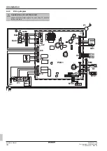
Page 14: ...2021 09 4 8 6 Wiring diagram DANGER RISK OF ELECTROCUTION Disconnect the power supply for more than 10 minutes before servicing X1A X2 X4 X5 X1M X2M X6A X7 1 1 1 1 1 1 1 1 1 1 1 1 1 X12 X10 X11 X17 X1...

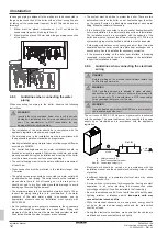
Page 15: ...7 Guidelines when connecting the condensate piping DANGER In order to prevent escape of flue gases and so poisoning the condensate trap must be mounted to its place before commissioning Condensate tra...

Page 16: ...ial to ensure that products of combustion discharging from the terminal cannot re enter the building or other buildings through ventilators windows doors other sources of natural air infiltration or f...

Page 17: ...rom separate combustion and air supply circuits shall fit inside a square of 50 cm and the distance between the planes of the two orifices shall be less than 50 cm a b e c c d d f g h L i a Roof termi...

Page 18: ...ncentric flue system INFORMATION C63 flue type is not applicable to Belgium To install the boiler as a C63x option the following data must be used to determine the correct diameters and lengths of the...

Page 19: ...flue system The boiler draws combustion air from outside via a separate supply pipe routed through the external wall and expels flue gas to a shared flue system The multi served chimney is a system t...

Page 20: ...P4811 30 elbow 60 100 EKFGP4664 30 elbow 80 125 EKFGP4814 Extension duct 60 100 500 mm EKFGP4651 1000 mm EKFGP4652 Extension duct 80 125 500 mm EKFGP4801 1000 mm EKFGP4802 Tile roof outlet kit 60 100...

Page 21: ...crews on the radiators Make sure screws are tightened after venting a a Filling valve 8 If after the venting the pressure decreases below 0 8 bar refill the system with water until the pressure reache...

Page 22: ...ck the CO2 values at minimum capacity 5 Press CH to switch to maximum capacity H caption will appear on screen Check the CO2 values at maximum capacity 6 To quit sweeper mode press Reset button The CO...

Page 23: ...unction of the boiler error mode Emphasise that if an error is indicated refer to Error codes in the operation manual Inform the user about frost protection function and advise never to cut off the el...

Page 24: ...ANBUL T RK YE Tel 0216 453 27 00 Faks 0216 671 06 00 a r Merkezi 444 999 0 Web www daikin com tr G lsuyu Mahallesi Fevzi akmak Caddesi Bur ak Sokak No 20 34848 Maltepe 3P469346 12R 2021 09 Copyright 2...

Reviews: