4 Installation
Installation Manual
12
D2CNL024A1AA
Wall-mounted condensing boiler
3P469346-12R – 2021.09
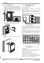
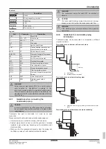
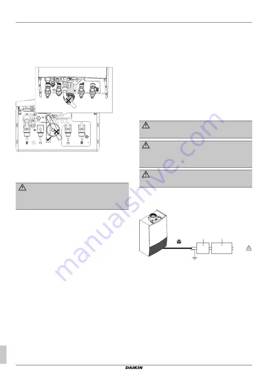
In case gas piping is adjacent to the wall and is to be connected to
the gas pipe connection of the boiler with an elbow, enough space
for taking out the condensate trap must be left. This can be done in
two ways:
1
Elbow must be placed crosswise so it will not block the
condensate trap when it is being taken out.
2
Elbow must be placed 120 mm below the gas piping connection
of the boiler.
4.8.3
Guidelines when connecting the water
piping
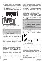
When connecting the piping to the boiler, observe the following
instructions:
WARNING
Ignoring the rules explained below may result in serious
damages in installation or boiler or cause discomfort of the
user. The manufacturer is NOT responsible for any
damage that may occur this way.
▪ The installation of the boiler should be in compliance with the
applicable legislation, standards, and regulations.
▪ The materials used in the installation must be in compliance with
the applicable legislation, standards, and regulations.
▪ Heating installation piping material must not allow oxygen diffusion
according to DIN4726.
▪ The central heating/domestic hot water installation should be
flushed and visually inspected. Wastes, dust, rubbers, and metal
pieces generated during the installation and mounting of the boiler
must be removed in order not to cause any damage.
▪ The central heating circuit must be able to withstand a pressure of
at least 6 bar.
▪ Cross connection must be preferred in the radiators longer than
1.5 metres.
▪ The safety valve piping should be connected to a water outlet with
an additional hose or piping. This outlet should not be installed in
places where there is risk of freezing, nor in the rain gutter, it
should not end to dry floor without available drainage to avoid
damaging of floor coating like parquet.
▪ The maximum pressure in the domestic hot water circuit is 10 bar.
Inspect the piping taking this in to consideration. If the water
pressure of the main water supply is excessive, use an
appropriate pressure reducer. Installation must comply with
EN 15502-2-2.
▪ As the condensing boilers generate condensate, the condensate
trap outlet should be connected to an open drain. Piping and
elements of the drain line must be made of acid-resistant material
like plastics. Metals like steel or copper are not allowed.
▪ The system must be air-free to protect the boiler. There are two
automatic air vents on the boiler, one at heat exchanger, the other
on the pump. Ensure air is discharged completely at each water
filling. Bleed the radiators if necessary.
▪ If the boiler will be connected to an old central heating/domestic
hot water installation, then first visually inspect the old installation.
The installation must be in compliance with the capacity of the
boiler and must not prevent the efficient running of it. Dirt in old
system and piping must be flushed, and filters must be inspected.
▪ If old piping material does not have oxygen barrier, then it must be
separated from the boiler circuit via a plate heat exchanger and a
second pump has to be installed for necessary circulation.
▪ If the pressure reading on the boiler user interface is dropping
repeatedly, most probably there is a leakage in the installation.
Inspect the installation to repair.
4.8.4
Guidelines when connecting the electrical
wiring
DANGER
Before working on the electrical circuit always isolate the
unit from the power mains.
WARNING
ONLY qualified persons are allowed to make electrical
connections on the unit. Failure to observe this warning will
void the warranty. The manufacturer is NOT responsible
for any damage that may occur this way.
WARNING
Use a dedicated power circuit. NEVER use a power supply
cable shared by another unit.
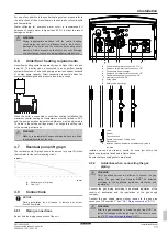
The unit runs on 230 V AC 50 Hz power. A power cable is delivered
with the package. The power cable must be connected to the power
supply by an electrician and in accordance with the applicable
legislation.
a
b
3×0.75 TTR / 230 V
H05RN
1~ 230 V
50 Hz
Cat. III
a
Safety breaker (2 A)
b
Earth leakage safety breaker
Cat. III
Overvoltage category III
▪ Electrical work should be carried out in accordance with the
installation manual and the national electrical wiring rules or code
of practice.
▪ Insufficient capacity or incomplete electrical work may cause
electrical shock or fire.
▪ A main switch or other means for disconnection, having a contact
separation in all poles providing full disconnection under
overvoltage category III, shall be installed in the fixed wiring.
▪ Be sure to establish an earth. Do not earth the unit to a utility pipe,
lightning arrester, or telephone earth.
Incomplete earth may
cause electrical shock and fire.
▪ While the electrical connections are being done, energy should
not be on the main power supply cable and the main switch
should be closed.
▪ During the electrical connections, make sure that the cables are
well-fixed and are connected firmly and tightly.


