background image

13

*Apply force to the center of the span.

t = Span length, inches     


C = Center distance, inches

D = Larger sheave diameter, inches

d = Smaller sheave diameter, inches

h = Deflection height, inches

DRIVE BELT TENSION ADJUSTMENT

BELT

DRIVE

Used

New

DBH/DBC090*V

2.6 to 3.6

4.5+/-.5

5.5+/-.5

1/4+/-1/16

DBH/DBC090*S

3.0 to 4.0

4.5+/-.5

5.5+/-.5

1/4+/-1/16

DBH/DBC102*V

2.6 to 3.6

4.5+/-.5

5.5+/-.5

1/4+/-1/16

DBH/DBC102*S

3.0 to 4.0

4.5+/-.5

5.5+/-.5

1/4+/-1/16

DBH/DBC120*V

2.6 to 3.6

4.5+/-.5

5.5+/-.5

1/4+/-1/16

DBH/DBC120*S

3.0 to 4.0

4.5+/-.5

5.5+/-.5

1/4+/-1/16

DBC150*V

3.0 to 4.0

4.5+/-.5

5.5+/-.5

1/4+/-1/16

DBC150*S

4.2 to 5.2

4.5+/-.5

5.5+/-.5

1/4+/-1/16

A

Standard

MODEL

DEFLECTION 

(in)

TYPE

 SHEAVE 

DIAMETER (d) (in)

DEFLECTION FORCE (lbs)

Recommended Pounds of Force Per Belt 

When new V-belts are installed on a drive the initial 

tension will drop rapidly during the first few hours. Check 

tension frequently during the first 24 hours of operation. 

Subsequent re-tensioning should fall between the minimum 

and maximum force. To determine the deflection distance 

from the normal position, use a straightedge or stretch a 

cord from sheave to sheave to use as a reference line. On 

multiple belt drives, an adjacent undeflected belt can be 

used as a reference.

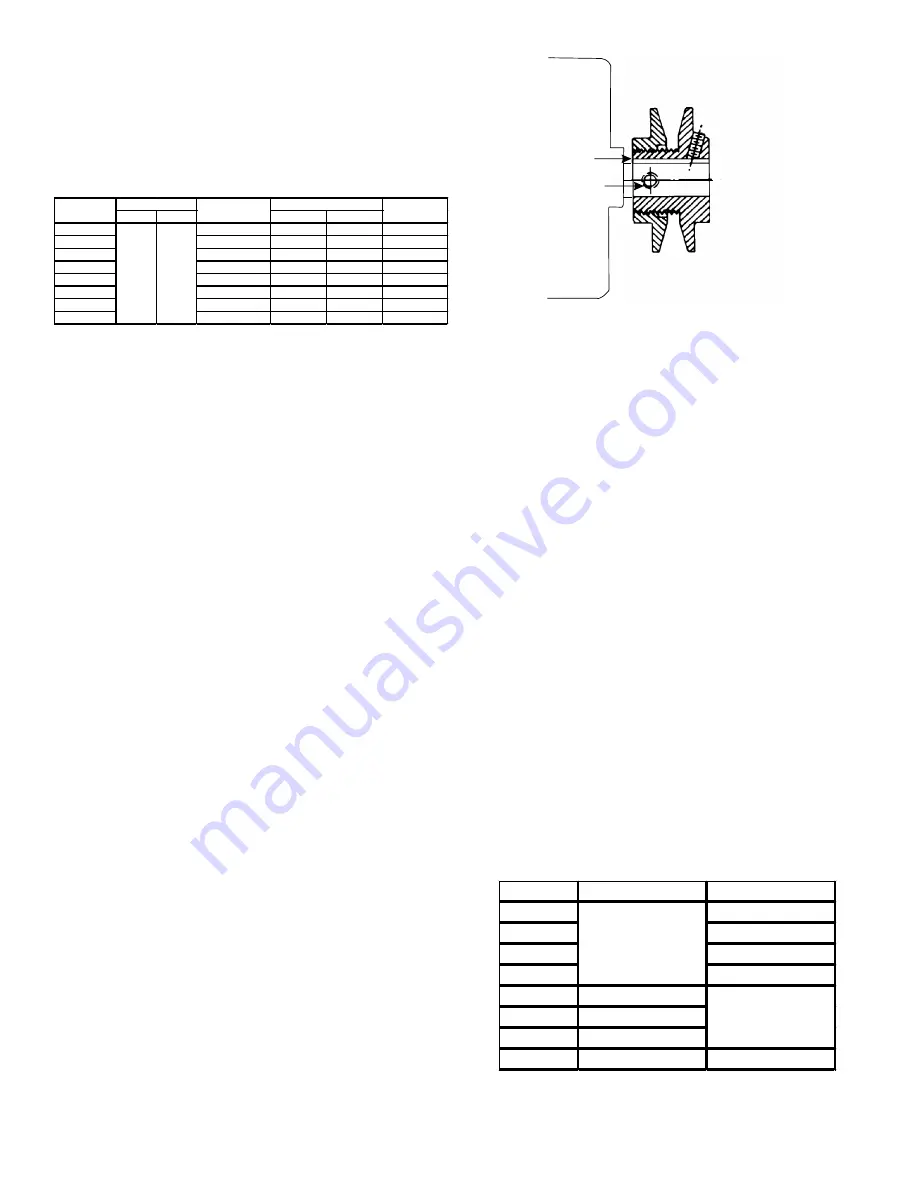
MOTOR SHEAVE ADJUSTMENTS

Vl, Vm & 2vp Variable Pitch Key Type Motor 

Sheaves

The driving and driven sheaves should be in alignment with 

each other and the shafts parallel.

Vl & Vm Sheaves Adjustment

1. 

Loosen set screw “B” using a 5/32” Allen key.

2.  Making half or full turns from closed position, adjust 

sheave pitch diameter for desired speed. DO NOT 

OPEN MORE THAN SIX FULL TURNS.

3. 

Tighten set screw “B” securely over flat.

4.  Carefully put on belts and adjust belt tension. DO 

NOT FORCE BELTS OVER GROOVES.

5. 

Ensure all keys are in place and the set screws tight 

before starting drive. Recheck set screws and belt 

tension after 24 hours service.

NOTE: Future adjustments should be made by 

loosening the belt tension and increasing or 

decreasing the pitch diameter of the sheave by 

half or full turns as required. Readjust belt 

tension before starting drive.

C

B

VL & VM

NOTE: Do not operate sheave with flange 

projecting beyond the hub end.

Electrical Input Check

Make preliminary check of evaporator fan ampere draw 

and verify that motor nameplate amps are not exceeded. A 

final check of amp draw should be made upon completion 

of air balancing of the duct system (see Appendix B).

Refrigeration System Checks

Heat pump units are equipped with thermal expansion 

valves. 

Ensure the hold-down bolts on the compressor are secure 

and have not vibrated loose during shipment.  Check 

that the vibration grommets have been installed and 

visually check all piping for damage and leaks and repair 

if necessary.  The entire system has been factory charged 

and tested, making it unnecessary to field charge.  Factory 

refrigerant charge is shown on the unit’s nameplate.

To confirm charge levels or, if a leak occurs and charge 

needs to be added to the system, it is recommended to 

evacuate the system and recharge refrigerant to the unit’s 

nameplate specifications.  This unit has been rated in 

the cooling mode at the AHRI rated conditions of:  indoor 

(80°F db/67°F wb) and outdoor (95°F db).  While operating 

at this condition, the superheat (measured at the suction 

service port located near the compressor) or the subcool 

(measured at the outdoor liquid line port) should be within 

the range given in the following table.

Unit

Subcool (°F)

Superheat (°F)

DBC090*

11 to 15

DBC102*

10 to 14

DBC120*

10 to 14

DBC150*

11 to 17

DBH090*

3 to 7

DBH102*

13 to 17

DBH120*

9 to 13

DBH150*

10 to 14

20 to 25

N/A

10 to 15

Summary of Contents for DBC Series

Page 1: ...erty damage arising from improper service or service procedures If you service this unit you assume responsibility for any injury or property damage which may result In addition in jurisdictions that...

Page 2: ...B Electrical Data 27 Appendix C Unit Dimensions 40 Appendix D Min Max Airflow 41 Wiring Diagram 42 Start Up Checklist 44 To The Installer Before installing this unit please read this manual to familia...

Page 3: ...cepted industry guides such as the ASHRAE Handbooks The manufacturer assumes no responsibility for equipment installed in violation of any code or regulation The mechanical installation of the package...

Page 4: ...tly on wood floors or on Class A Class B or Class C roof covering material To avoid possible personal injury a safe flat surface for service personnel should be provided As indicated on the unit data...

Page 5: ...rk must be constructed using industry guidelines The duct work must be placed into the roof curb before mounting the package unit Our full perimeter curbs include duct connection frames to be assemble...

Page 6: ...nit base frame from fork lift damage Removal is accomplished by extracting the sheet metal retainers and pulling the struts through the base of the unit Refer to rigging label on the unit Your unit ma...

Page 7: ...65 302 Corner Weight B 359 347 344 401 Corner Weight C 267 300 317 312 Corner Weight D 302 311 290 379 Unit Shipping Weight 1227 1287 1291 1394 Unit Operating Weight 1152 1212 1216 1314 X inches 43 44...

Page 8: ...ree wire The unit is factory wired for the voltage shown on the unit s data plate NOTE If supply voltage is 208V lead on primary of transformer s must be moved from the 230V to the 208V tap Refer to w...

Page 9: ...holes in the unit base must be sealed including those around conduit nuts to prevent water leakage into building All required conduit and fittings are to be field supplied Supply voltage to roof top...

Page 10: ...connection is supplied on the end of the unit and bottom of the drain pan for condensate piping An external trap must be installed for proper condensate drainage Hand tighten drain fitting to the drai...

Page 11: ...installation instructions All electric power all gas hot water or steam line connections and the condensate drain installation have been made to each unit on the job These main supply lines must be f...

Page 12: ...run high stage CFM below 300 CFM per ton evaporator freezing or poor unit performance is possible Evaporator Fan Rotation Check Check that fan rotates clockwise when viewed from the drive side of unit...

Page 13: ...GROOVES 5 Ensure all keys are in place and the set screws tight before starting drive Recheck set screws and belt tension after 24 hours service NOTE Future adjustments should be made by loosening th...

Page 14: ...ly checked so postpone the test to another day when conditions are more suitable but DO NOT FAIL TO TEST If the outdoor ambient is low and the unit operates properly on the heating cycle you may check...

Page 15: ...dels with V or S in the 8th position of the model number For 2 speed models the indoor blower will operate on low speed when in Fan Only mode or while in first stage Cooling mode Unit will operate on...

Page 16: ...also act as check valves to allow for the reverse of refrigerant flow When the heat pump is on the heating cycle the outdoor coil is functioning as an evaporator The temperature of the refrigerant in...

Page 17: ...rently have sharp edges and it is necessary that the installer and service personnel exercise caution Preventive maintenance is the best way to avoid unnecessary expense and inconvenience Have this sy...

Page 18: ...allow air entering the indoor coil to drop below 65 F Air below this temperature will cause low discharge pressure thus low suction pressure and excessive defrost cycling resulting in low heating outp...

Page 19: ...1 51 2481 1003 1 28 DBC090 S HIGH STATIC HORIZONTAL1 ESP In H2O TURNS OPEN 0 1 2 3 4 5 1 To operate below 0 8 H2O external static pressure motor and blower sheave must be changed to VL40 and AK84H re...

Page 20: ...44 1 8 3732 1096 2 32 2781 1053 1 51 ESP In H2O TURNS OPEN 0 1 2 3 4 5 1 To operate below 0 8 H2O external static pressure motor and blower sheave must be changed to VL40 and AK84H respectively or eq...

Page 21: ...O TURNS OPEN 0 1 2 3 4 5 1 To operate below 0 8 H2O external static pressure motor and blower sheave must be changed to VL40 and AK74H respectively or equivalents DBC120 V STANDARD STATIC DOWNSHOT1 CF...

Page 22: ...5348 1144 4 26 4928 1106 3 77 4389 1068 3 19 3762 1030 2 22 ESP In H2O TURNS OPEN 0 1 2 3 4 5 1 To operate below 0 8 H2O external static pressure motor and blower sheave must be changed to VP44 and AK...

Page 23: ...P CFM RPM BHP CFM RPM BHP 0 1 3532 620 1 05 3276 600 0 78 0 2 3601 663 1 13 3264 620 0 93 2947 600 0 67 0 3 3654 707 1 18 3323 663 1 00 2955 620 0 81 2617 600 0 57 0 4 3728 748 1 24 3377 707 1 05 3011...

Page 24: ...2 83 2797 1058 2 10 DBH102 V STANDARD STATIC DOWNSHOT1 CFM RPM BHP CFM RPM BHP CFM RPM BHP CFM RPM BHP CFM RPM BHP CFM RPM BHP 0 1 3933 610 1 29 0 2 4039 655 1 46 3658 611 1 20 0 3 4172 693 1 66 3763...

Page 25: ...DOWNSHOT1 CFM RPM BHP CFM RPM BHP CFM RPM BHP CFM RPM BHP CFM RPM BHP CFM RPM BHP 0 1 4836 649 1 73 4463 610 1 41 0 2 4976 692 1 97 4557 650 1 60 4177 610 1 30 0 3 4641 693 1 82 4213 653 1 47 3783 61...

Page 26: ...2 5963 762 2 57 5529 721 2 24 5102 681 1 69 4625 642 1 43 0 3 5716 762 2 40 5241 721 2 06 4778 681 1 53 4276 642 1 27 0 4 5439 762 2 22 4929 721 1 87 4429 681 1 36 3910 642 1 12 0 5 5581 805 2 90 5131...

Page 27: ...24 30 1 20 7 25 4 3 1 25 30 27 9 30 4 3 33 3 35 1 29 2 30 4 3 1 34 6 35 50 5 60 4 3 55 9 60 1 51 7 60 4 3 1 57 1 60 73 80 4 3 78 4 80 1 74 3 80 4 3 1 79 7 80 18 3 20 4 3 22 6 25 1 19 3 20 4 3 1 23 6...

Page 28: ...0 45 9 45 6 50 50 9 6 8 7 3 3 3 0 55 5 54 3 60 60 46 6 52 6 50 60 9 6 8 7 58 6 63 5 60 70 3 3 3 0 50 7 56 4 60 60 9 6 8 7 3 3 3 0 62 7 67 2 70 70 85 7 97 7 90 100 9 6 8 7 97 7 109 100 110 3 3 3 0 89 8...

Page 29: ...25 1 2 18 5 20 3 5 1 2 22 25 21 25 3 5 25 4 30 1 2 22 5 25 3 5 1 2 26 9 30 39 1 40 3 5 43 5 45 1 2 40 6 45 3 5 1 2 45 45 57 1 60 3 5 61 5 70 1 2 58 6 60 3 5 1 2 63 70 Model Number Electrical Rating C...

Page 30: ...35 1 24 5 30 4 3 1 28 8 35 27 9 30 4 3 33 3 35 1 29 2 30 4 3 1 34 6 35 50 5 60 4 3 55 9 60 1 51 7 60 4 3 1 57 1 60 73 80 4 3 78 4 80 1 74 3 80 4 3 1 79 7 80 22 1 25 4 3 26 4 30 1 23 1 25 4 3 1 27 4 30...

Page 31: ...60 6 60 3 70 70 9 6 8 7 3 3 3 0 70 2 69 0 80 80 57 3 57 3 70 70 9 6 8 7 66 9 67 4 80 80 3 3 3 0 60 6 60 3 70 70 9 6 8 7 3 3 3 0 70 2 71 1 80 80 89 6 102 90 110 9 6 8 7 102 112 110 125 3 3 3 0 93 7 10...

Page 32: ...1 2 23 4 25 3 5 1 2 26 9 30 22 4 25 3 5 26 8 30 1 2 23 9 25 3 5 1 2 28 3 30 40 5 45 3 5 44 8 45 1 2 42 45 3 5 1 2 46 3 50 58 5 60 3 5 62 9 70 1 2 60 70 3 5 1 2 64 4 70 Model Number Electrical Rating...

Page 33: ...22 2 25 4 3 1 26 5 30 43 8 45 4 3 48 1 50 1 44 8 45 4 3 1 49 1 50 66 3 70 4 3 70 6 80 1 67 3 70 4 3 1 71 6 80 88 9 90 4 3 93 2 100 1 89 9 90 4 3 1 94 2 100 19 8 25 4 3 24 1 30 1 20 8 25 4 3 1 25 1 30...

Page 34: ...0 48 9 48 6 60 60 9 6 8 7 3 3 3 0 58 5 57 3 60 60 84 7 90 7 90 100 9 6 8 7 94 3 99 4 100 100 3 3 3 0 88 0 93 7 90 100 9 6 8 7 3 3 3 0 97 6 102 100 110 124 136 125 150 9 6 8 7 133 145 150 150 3 3 3 0...

Page 35: ...26 5 30 1 2 24 2 25 3 5 1 2 27 7 30 41 45 3 5 44 5 45 1 2 42 2 45 3 5 1 2 45 7 50 59 60 3 5 62 5 70 1 2 60 2 70 3 5 1 2 63 7 70 77 1 80 3 5 80 6 90 1 2 78 3 80 3 5 1 2 81 8 90 Model Number Electrical...

Page 36: ...1 24 4 30 4 3 1 28 7 30 45 9 50 4 3 50 2 60 1 46 9 50 4 3 1 51 2 60 68 5 70 4 3 72 8 80 1 69 5 70 4 3 1 73 8 80 91 100 4 3 95 3 100 1 92 100 4 3 1 96 3 100 22 25 4 3 26 3 30 1 23 25 4 3 1 27 3 30 44...

Page 37: ...3 5 60 5 70 1 2 58 2 60 3 5 1 2 61 7 70 75 1 80 3 5 78 6 80 1 2 76 3 80 3 5 1 2 79 8 80 EH B 7M46 45 43 3 DBH1207S 575 3 60 2 5 1 39 5 2 0 33 3 5 2 speed Belt Drive High Static 3 3 5 EH B 7M16 15 14...

Page 38: ...5 9 6 8 7 3 3 3 0 156 167 175 175 182 200 200 225 9 6 8 7 192 209 200 225 3 3 3 0 186 203 200 225 9 6 8 7 3 3 3 0 195 212 200 225 33 2 40 4 3 37 5 45 1 34 2 40 4 3 1 38 5 45 55 7 60 4 3 60 70 1 56 7 6...

Page 39: ...30 40 8 45 3 5 44 3 45 1 2 42 45 3 5 1 2 45 5 50 58 9 60 3 5 62 4 70 1 2 60 1 70 3 5 1 2 63 6 70 76 9 80 3 5 80 4 90 1 2 78 1 80 3 5 1 2 81 6 90 Optional Powered Convienience Optional Power Exhaust Po...

Page 40: ...d on the flanges around the duct openings and the gasket is APPENDIX C UNIT DIMENSIONS Horizontal Discharge Vertical Discharge Bottom of Unit NOTE For horizontal discharge remove supply and return duc...

Page 41: ...903S 2400 X X X X X X DBC0904S 2400 X X X X X X DBC0907S 2400 X X X X X X DBC1023S 2750 X X X X X X DBC1024S 2750 X X X X X X DBC1027S 2750 X X X X X X DBC1203S 3250 X X X X X X DBC1204S 3250 X X X X...

Page 42: ...ITH PINK STRIPE BR BROWN GR GREEN GY GRAY OR ORANGE PK PINK PU PURPLE RD RED TN TAN WH WHITE YL YELLOW YL PK YELLOW WITH PINK STRIPE POWER AND CONTROLS WIRING DIAGRAM DBH 090 120 LINE VOLTAGE 208 230...

Page 43: ...G IN JUMPER PLUG AT THE LAST SAFETY DEVICE INSTALLED IF A THIRD PARTY SAFETY DEVICE IS FIELD INSTALLED CUT THE RED WIRE ON THE JUMPER PLUG AND WIRE A NORMALLY CLOSED DRY CONTACT IN SERIES WITH THE CUT...

Page 44: ...44...

Page 45: ...45...

Page 46: ...46 THIS PAGE IS INTENTIONALLY LEFT BLANK...

Page 47: ...47 THIS PAGE IS INTENTIONALLY LEFT BLANK...

Page 48: ...2020 19001 Kermier Rd Waller TX 77484 www daikincomfort com CUSTOMER FEEDBACK Daikin is very interested in all product comments Please fill out the feedback form on the following link https daikincom...

Reviews: