15
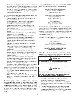
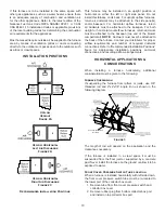
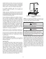
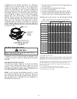
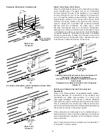
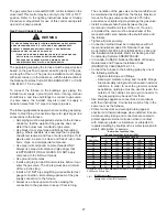
COMBUSTION AIR INTAKE OPTIONS: The RF000142
coupling can be secured directly to the furnace intake
coupling if condensation is a concern. If the RF000142 is
used on the combustion air inlet, it must be installed with
the arrow pointing up. It should be noted, the combustion air
will actually be moving in a direction opposite of the arrow
on the RF000142 coupling. It must have a field supplied,
trapped drain tube free-draining to proper condensate
disposal location. A loop in the drain tube can serve as a
trap. The unused RF000142 drain fitting should be capped.
(Figure 8B) A tee installed in the intake pipe is also an
acceptable method of catching condensation. It must have
a field supplied, trapped drain tube or pipe, free-draining to
proper condensate disposal location. A loop in the drain tube
can serve as a trap.
VENT-DRAIN
The RF000142 Coupling
Figure 8B
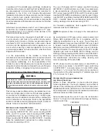
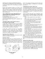
Non-Direct Vent Installations
WARNING
Edges of sheet metal holes may be sharp. Use gloves as a
precaution when removing plugs.
A minimum of one 90° elbow should be installed on the
combustion air intake “coupling” to guard against inadvertent
blockage.
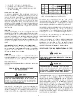
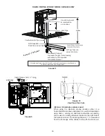
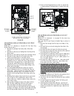
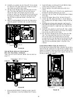
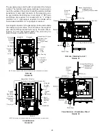
Alternate Vent/Flue Location
The alternate vent/flue location is the large hole directly
in line with the induced draft blower outlet. To use the
alternate vent/flue location refer to the following steps and
the “Alternate Vent/Flue Location” figure. This feature is not
currently available on counterflow models.
NOTE:
In the horizontal left installation position, a means
of condensate collection must be provided to keep vent
pipe condensate from entering the draft inducer housing. If
the vent drain elbow is eliminated from the installation, an
RF000142 kit must be used.
1. Remove the four screws from the vent pipe flange on
top the furnace.
2. Remove the internal elbow and vent pipe
3. Cut 2 ½” from the flange.
4. Remove plastic plug in line with the inducer outlet
5. Install cut end of the flanged section and connect to
inducer with rubber coupling supplied with furnace.
Install screws removed in step 1 securing flange to cabinet.
MODEL
PIPE
SIZE
1
2
3
4
5
6
7
8
2
75
70
65
60
55
50
45
40
3
114
107
100
93
86
79
72
65
2
145
140
135
130
125
120
115
110
3
168
161
154
147
140
133
126
119
2
55
50
45
40
35
30
25
20
3
127
120
113
106
99
92
85
78
2
^
30
25
20
15
10
5
N/A
N/A
3
^
72
65
58
51
44
37
30
23
2
^
30
25
20
15
10
5
N/A
N/A
3
^
72
65
58
51
44
37
30
23
2
^
40
35
30
25
20
15
10
5
3
72
65
58
51
44
37
30
23
2
60
55
50
45
40
35
30
25
3
168
161
154
147
140
133
126
119
2
30
25
20
15
10
5
N/A
N/A
3
113
106
99
92
85
78
71
64
2
N/A
N/A
N/A
N/A
N/A
N/A
N/A
N/A
3
65
58
51
44
37
30
23
16
2
100
95
90
85
80
75
70
65
3
137
130
123
116
109
102
95
88
2
60
55
50
45
40
35
30
25
3
127
120
113
106
99
92
85
78
2
35
30
25
20
15
10
5
N/A
3
160
153
146
139
132
125
118
111
2
N/A
N/A
N/A
N/A
N/A
N/A
N/A
N/A
3
127
120
113
106
99
92
85
78
DC92SS0804CN
DC92SS1005CN
DM92SS0805CN
DM92SS1004CN
DM92SS1005CN
DM92SS1205DN
DC92SS0402BN
DC92SS0603BN
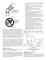
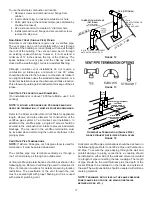
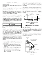
DM92SS* / DC92SS* Direct Vent (2-Pipe) & Non-Direct Vent (1-Pipe)
(6)
Maximum Allowable Length of Vent/FLue Pipe & Combustion Air Pipe (Ft)
(1) (2)
ELBOWS
DM92SS0403AN
DM92SS0603BN
DM92SS0803BN
DM92SS0804CN
DM92SS0402BN
7,000 ft altitude or above use 3" pipe
^ DM92SS0803BN - add 10' of 2" pipe for up flow position, add 66' of 3" pipe for up flow position
^ DM92SS0805CN - add 15' of 2" pipe fpr upflow position, add 58' of 3" pipe for upflow position
^ DM92SS0804CN - add 25' of 2" pipe for up flow position, add 58' of 3" pipe for up flow position
1) Maximum allowable limits listed on individual lengths for inlet and flue and NOT a combination.
2) Minimum requirement for each vent pipe is five (5) feet in length and one elbow/tee.
3) Tee used in the vent/flue termination must be included when determining the number of
elbows in the piping system.
4) 2 1/2" or 3" diameter pipe can be used in place of 2" diameter pipe.
5) Increased Clearance Configurations using (2) 45 deg. Long Sweep elbows should be
considered equivalent to one 90 deg. elbow


