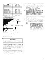
31
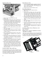
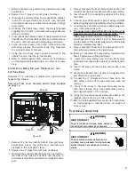
AUX OUT
AUX IN
L1
NEUTRAL
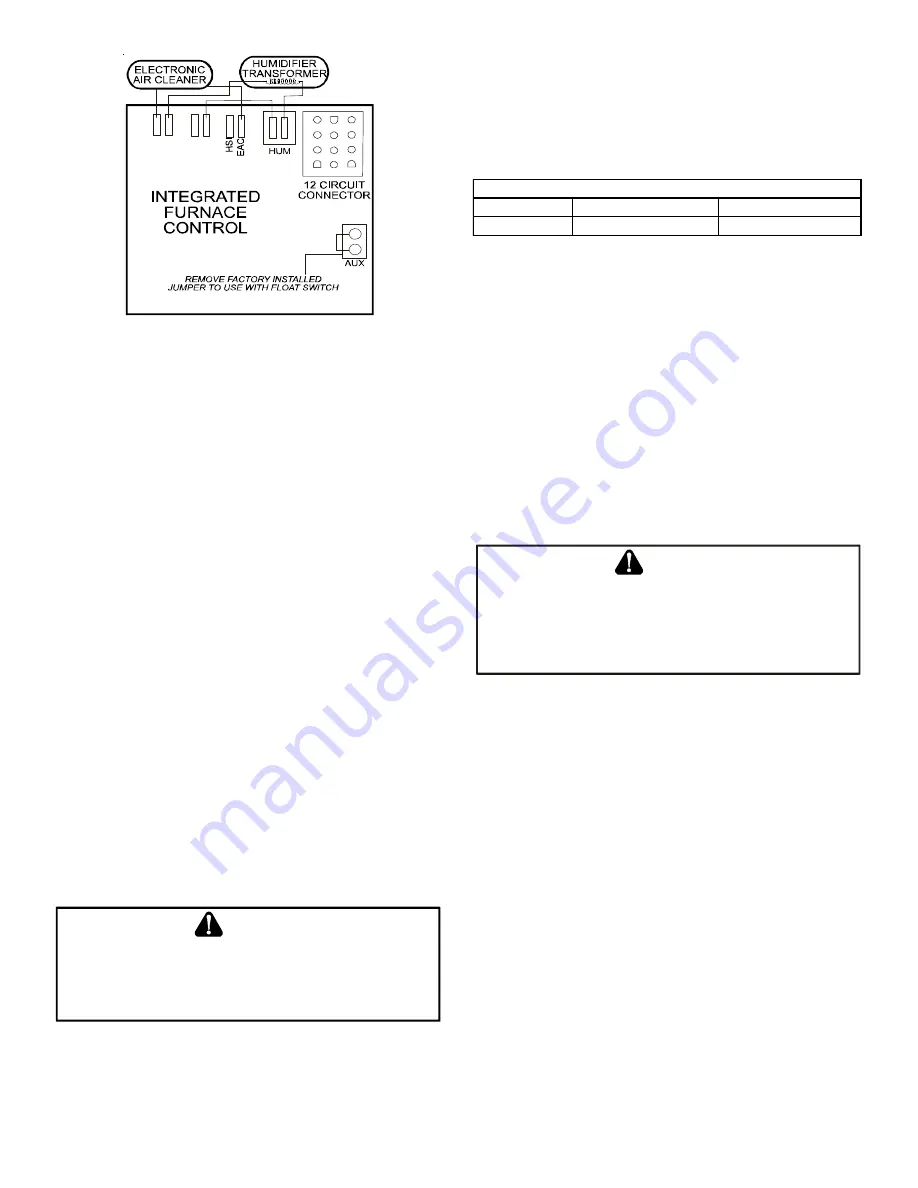
Accessories Wiring
Figure 35
If it is necessary for the installer to supply additional line voltage
wiring to the inside of the furnace, the wiring must conform to
all local codes, and have a minimum temperature rating of 105°C.
All line voltage wire splices must be made inside the furnace
junction box.
The furnace control board HUM (dry contacts) are closed
whenever the inducer is energized in a non-communicat-
ing installation. When used with a CTK02**, CTK03 or
CTK04 communicating thermostat, the HUM terminals are
closed whenever there is a call for humidity when this
feature is enabled in the communicating thermostat. In
the CTK03AB & CTK04** humidity must be enabled in he
main menu, se up in the Installer menu & ComfortNet
user menu. The integrated control module electronic air
cleaner terminals (EAC) are energized with 115 volts when-
ever the circulator blower is energized.
24 V
OLT
H
UMIDIFIER
A 24 volt humidifier can be powered by feeding one of the
HUM terminals with a field installed wire from the R ter-
minal.
G
AS
S
UPPLY
AND
P
IPING
The furnace rating plate includes the approved furnace gas input
rating and gas types. The furnace must be equipped to operate
on the type of gas applied. This includes any conversion kits
required for alternate fuels and/or high altitude.
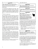
CAUTION
T
O
PREVENT
UNRELIABLE
OPERATION
OR
EQUIPMENT
DAMAGE
,
THE
INLET
GAS
SUPPLY
PRESSURE
MUST
BE
AS
SPECIFIED
ON
THE
UNIT
RATING
PLATE
WITH
ALL
OTHER
HOUSEHOLD
GAS
FIRED
APPLIANCES
OPERATING
.
Inlet gas supply pressures must be maintained within the ranges
specified in the following table. The supply pressure must be
constant and available with all other household gas fired appli-
ances operating. The minimum gas supply pressure must be
maintained to prevent unreliable ignition. The maximum must
not be exceeded to prevent unit overfiring.
Natural Gas
Minimum: 4.5" w.c.
Maximum: 10.0" w.c.
Propane Gas
Minimum: 11.0" w.c.
Maximum: 13.0" w.c.
Inlet Gas Supply Pressure
A heat pump thermostat with
three stages of heat
is required
to properly use a two-stage furnace in conjunction with a
heat pump. Refer to the fossil fuel kit (AFE18-60A) installa-
tion instructions for additional thermostat requirements.
H
IGH
A
LTITUDE
D
ERATE
In some areas the gas supplier may artificially derate the gas
in an effort to compensate for the effects of altitude. If the
gas is artificially derated, the appropriate orifice size must be
determined based upon the BTU/ft
3
content of the derated
gas and the altitude. Refer to the National Fuel Gas Code,
NFPA 54/ANSI Z223.1 or CAN/CSA B149.1-15 in Canada, and
information provided by the gas supplier to determine the
proper orifice size.
P
ROPANE
G
AS
C
ONVERSION
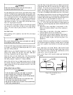
WARNING
P
OSSIBLE
PROPERTY
DAMAGE
,
PERSONAL
INJURY
OR
DEATH
MAY
OCCUR
IF
THE
CORRECT
CONVERSION
KITS
ARE
NOT
INSTALLED
. T
HE
APPROPRIATE
KITS
MUST
BE
APPLIED
TO
ENSURE
SAFE
AND
PROPER
FURNACE
OPERATION
. A
LL
CONVERSIONS
MUST
BE
PERFORMED
BY
A
QUALIFIED
INSTALLER
OR
SERVICE
AGENCY
.
As shipped, this unit is configured for natural gas. The LPM-
09 is required to convert this furnace to operate on LP
gas.
The correct kit must be used to insure safe and proper fur-
nace operation. All conversions must be performed by a quali-
fied installer, or service agency.
G
AS
V
ALVE
This unit is equipped with a 24 volt gas valve which modulates
by pneumatic linkage to the combustion air blower. Taps for
measuring the gas supply pressure and manifold pressure are
provided on the valve. This is a non-convertible, non-adjust-
able gas valve equipped for natural gas.
The gas valve has a manual ON/OFF control located on the
valve itself. This control may be set only to the “ON” or
“OFF” position. Refer to the lighting instructions label or the
Startup Procedure & Adjustment
section of this manual for
use of this control during start up and shut down periods.


