56
SERVICING
Natural Gas
Minimum 4.5" w.c.
Maximum 10" w.c.
L.P. Gas
Minimum 10" w.c.
Maximum 13" w.c.
Inlet Gas Supply Pressure
Inlet Gas Supply Pressure
WARNING
D
ISCONNECT ELECTRICAL POWER AND SHUT OFF GAS SUPPLY.
1. Turn off gas supply to the furnace at the manual gas
shutoff valve external to the furnace.
2. Turn off electrical power to furnace.
3. Connect a manometer or appropriate gas pressure
gauge to the 1/8" NPT inlet pressure tap on the gas
valve.
4. Connect a second manometer or appropriate gas pres-
sure gauge to the 1/8" NPT outlet (manifold) pressure
tap on the gas valve.
5. Turn on gas supply to the furnace and verify inlet ma-
nometer connection is leak free before proceeding.
6. Set control board DIP switch #13 to “ON”
7. Jumper R to W1 on control board low volt terminal strip.
8. Turn on all gas appliances before starting furnace to
verify adequate supply pressure.
9. Turn on electrical power to the furnace. Observe and
record the gas supply pressure during ignition. If gas
supply pressure is not within the range shown above,
contact your gas supplier to correct the gas supply pres-
sure; do not make adjustments to the gas valve.
10. If gas supply pressure is within the acceptable range,
proceed with gas manifold pressure check.
NOTE:
Normal firing rate sequence is as follows for
DIP switch #13 in the “ON” position and 24 volts on
W1; a) Trial for ignition & flame stabilization period –
approximately 17 seconds at 80% rate. b) 35% rate for
approximately 2 minutes. c) 50% rate for 8 minutes.
11. Observe and record gas manifold pressure during the
50% firing rate. The gas manifold pressure at 50% fir-
ing rate must be within the appropriate range shown
below. If manifold pressure is found to be within the
acceptable range, do not adjust gas valve.
Natural Gas
Minimum .9" w.c.
Maximum 1.2" w.c.
L.P. Gas
Minimum 2.6" w.c.
Maximum 3.3" w.c.
Manifold Gas Pressure @ 50% Firing Rate
Manifold Gas Pressure
12. If manifold pressure is found to be lower than accept-
able (less than .9" wc for natural gas, less than 2.6"
WC for LP gas) turn the fine adjustment screw coun-
terclockwise slightly (¼ - ½ turn) and observe mani-
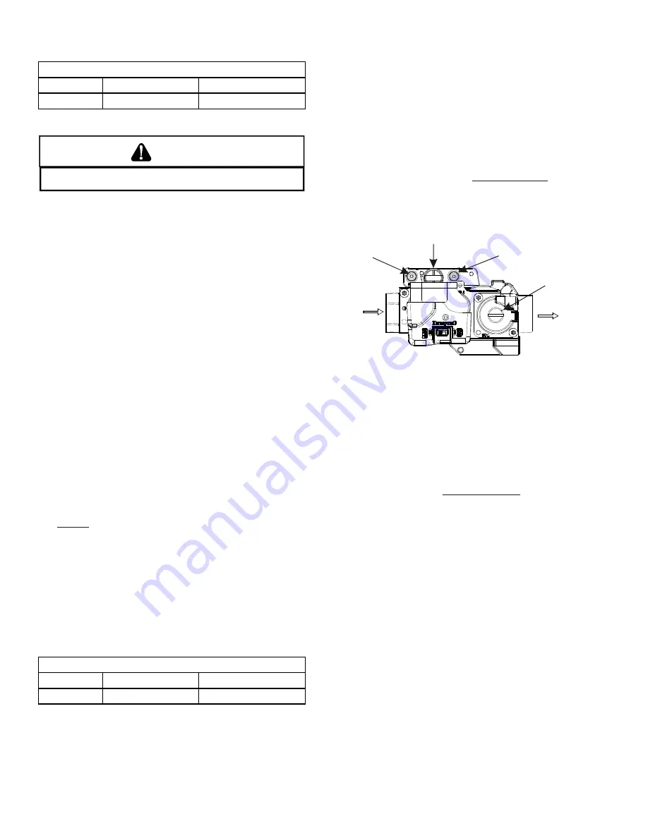
fold pressure. The fine adjustment screw is located
between the atmospheric and negative air ports and
extends from the base of the valve as shown in the
illustration below. Adjust in small increments using the
fine adjustment screw only, until manifold pressure is
within the acceptable range.
DO NOT ADJUST
the max
regulator screw located on top the gas valve.
DIRECTION
FLOW
Negative
Pressure Port
Gas Inlet
Atmospheric
Port
DO NOT
ADJUST
Follow procedure in this document
and
ADJUST HERE
13. If manifold pressure is found to be higher than accept-
able (more than 1.2" wc for natural gas, more than
3.3" WC for LP gas) turn the fine adjustment screw
clockwise slightly (¼ - ½ turn) and observe manifold
pressure. The fine adjustment screw is located between
the atmospheric and negative air ports and extends
from the base of the valve as shown in the illustration
below. Adjust in small increments using the fine ad-
justment screw only, until manifold pressure is within
the acceptable range.
DO NOT ADJUST
the max regu-
lator screw located on top the gas valve
S-304A CHECKING INDUCTOR COIL
Wired in series with ¾ and 1 HP ECM motors; the inductor
coil conditions the power supply to the motor, smoothing
out spikes and electrical noise. With voltage applied to
one side of the inductor coil, the output voltage to the
motor should be the same as incoming voltage.


