8
NOTE:
If supply voltage is 208V, all leads on primary of
transformer(s) must be moved from the 230V to the 208V tap.
Main power wiring should be sized for the minimum circuit
ampacity shown on the unit’s data plate. Size wires in accordance
with the ampacity tables in Article 310 of the National Electrical
Code. If long wires are required, it may be necessary to increase
the wire size to prevent excessive voltage drop. Wires should be
sized for a maximum of 3% voltage drop.
CAUTION
T
O AVOID PROPERTY DAMAGE OR PERSONAL INJURY DUE TO FIRE, USE
ONLY COPPER CONDUCTORS.
L
ABEL
ALL
WIRES
PRIOR
TO
DISCONNECTION
WHEN
SERVICING
CONTROLS
. W
IRING
ERRORS
CAN
CAUSE
IMPROPER
AND
DANGEROUS
OPERATION
. V
ERIFY
PROPER
OPERATION
AFTER
SERVICING
.
CAUTION
NOTE:
A weather-tight disconnect switch, properly sized for the
unit total load, must be field or factory installed. An external field
supplied disconnect may be mounted on the exterior panel.
Ensure the data plate is not covered by the field-supplied
disconnect switch.
• Some disconnect switches are not fused. Protect the
power leads at the point of distribution in accordance with
the unit’s data plate.
• The unit must be electrically grounded in accordance with
local codes or, in the absence of local codes, with the latest
edition of the National Electrical Code (ANSI-NFPA 70). A
ground lug is provided for this purpose. Size grounding
conductor in accordance with Table 250-95 of the National
Electrical Code. Do not use the ground lug for connecting
a neutral conductor.
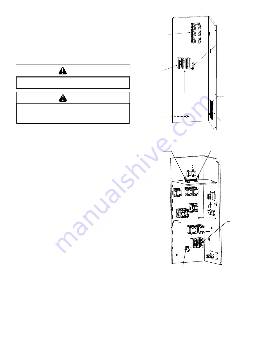
• Connect power wiring to the electrical middle contactor
within the main control box of power block, if equipped.
Low Voltage
Terminal Strip
Thermostat wiring
for all units
connect to low
voltage strip
Ground
Lug
Line voltage connects
to power block on
Coolers and the 230v
Gas Packs
Line voltage connects
to middle contactor
on 460v and 575v
Gas Packs
(or power block
if equipped)
Power Block
(Coolers &
230V Gas Packs
Only)
Field wiring enters
from this direction
POWER AND LOW VOLTAGE BLOCK LOCATIONS
Route field
control wiring
through
grommet
Field connection
for
control wiring
at
terminal block
HIGH
Ground Lug
LOW
Field wiring
enters from
this direction
Field
connection
for
line voltage
25 TON POWER AND LOW VOLTAGE BLOCK LOCATIONS
NOTE:
Depending on the options installed, the location of the com-
ponents may vary in some models.


