background image

57

MAINTENANCE

FLUE PASSAGES (QUALIFIED SERVICER ONLY)

At the start of each heating season, inspect and, if neces-
sary, clean the furnace flue passages.

FLAME SENSOR (QUALIFIED SERVICER ONLY)

Under some conditions, the fuel or air supply can create a
nearly invisible coating on the flame sensor. This coating
acts as an insulator, causing a drop in the flame sensing
signal. If this occurs, a qualified servicer must carefully clean
the flame sensor with steel wool. After cleaning, the flame
sensor output should be as listed on the specification sheet.

BURNERS

WARNING

HIGH


VOLTAGE

E

LECTRICAL COMPONENTS ARE CONTAINED IN BOTH

COMPARTMENTS. 

T

O AVOID ELECTRICAL SHOCK, INJURY OR

DEATH, DO NOT REMOVE ANY INTERNAL COMPARTMENT COVERS
OR ATTEMPT ANY ADJUSTMENT. 

C

ONTACT A QUALIFIED

SERVICE AGENT AT ONCE IF AN ABNORMAL FLAME
APPEARANCE SHOULD DEVELOP.

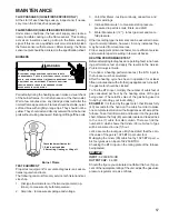
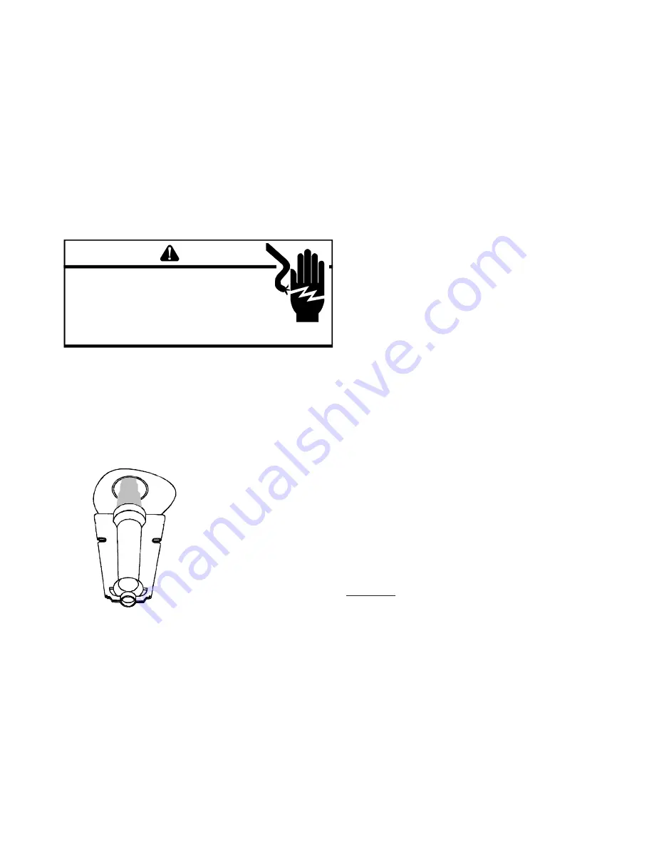
Periodically during the heating season make a visual check
of the burner flames. Turn the furnace on at the thermostat.
Wait a few minutes since any dislodged dust will alter the
normal flame appearance. Flames should be stable, quiet,
soft and blue with slightly orange tips. They should not be
yellow. They should extend directly outward from the burner
ports without curling downward, floating or lifting off the ports.

Check the burner flames for: 

1. Stable, soft and blue 

2. Not curling, floating, or lifting off. 

Burner Flame

TEST EQUIPMENT

Proper test equipment for accurate diagnosis is as essen-
tial as regular hand tools.

The following is a must for every service technician and ser-
vice shop.

1.

Dial type thermometers or thermocouple meter (op-
tional) - to measure dry bulb temperature.

2.

Amprobe - to measure amperage and voltage.

3.

Volt-Ohm Meter - testing continuity, capacitors, and
motor windings.

4.

Inclined Manometer - to measure static pressure,
pressure drop across coils, filters, and draft.

5.

Water Manometer (12") - to test gas inlet and mani-
fold pressure.

Other recording type instruments can be essential in solv-
ing abnormal problems, however, in many instances they
may be rented from local sources.

Proper equipment promotes faster, more efficient service
and accurate repairs resulting in fewer call backs.

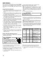
HEATING PERFORMANCE TEST

Before attempting to diagnose an operating fault, run a heat-
ing performance test and apply the results to the 

Service

Problem Analysis Guide.

To conduct a heating performance test, the BTU input to
the furnace must be calculated.

After the heating cycle has been in operation for at least
fifteen minutes and with all other gas appliances turned off,
the gas meter should be clocked.

To find the BTU input, multiply the number of cubic feet of
gas consumed per hour by the heating value of the gas
being used. (The calorific value of the gas being used is
found by contacting your local utility.)

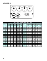
EXAMPLE:  

It is found by the gas meter, that it takes forty

(40) seconds for the hand on the cubic foot dial to make
one complete revolution, with all appliances off, except the
furnace. Take this information and locate it on the gas rate
chart. Observe the forty (40) seconds, locate and read across
to the one (1) cubic foot dial column. There we find the
number 90, which shows that ninety (90) cubic feet of gas
will be consumed in one (1) hour.

Let's assume the local gas utility has stated that the calo-
rific value of the gas is 1,025 BTU per cubic foot.

Multiplying the ninety (90) cubic feet by 1,025 BTU per cu-
bic foot gives us an input of 92,250 BTUH.

Checking the BTU input on the rating plate of the furnace
being tested.

EXAMPLE:
INPUT:

92,000 BTU/HR

OUTPUT CAP:

84,000

Should the figure you calculated not fall within five (5) per-
cent of the nameplate rating of the unit, adjust the gas valve
pressure regulator or resize orifices.

Summary of Contents for DD80VC

Page 1: ...l is to be used by qualified professionally trained HVAC technicians only Daikin does not assume any responsibility for property damage or personal injury due to improper service procedures or services performed by an unqualified person Service Instructions TM Copyright 2013 2014 2016 ...

Page 2: ...L INJURY OR DEATH IMPORTANTINFORMATION 3 4 PRODUCTIDENTIFICATION 5 9 ACCESSORIES 10 OPERATINGINSTRUCTIONS 11 13 PRODUCT DESIGN 14 37 SYSTEM OPERATION 38 42 TROUBLESHOOTING 43 48 SYSTEM OPERATION COMFORTNET 49 54 POLARIZATIONANDPHASING 55 MAINTENANCE 56 58 SERVICING 59 77 SERVICING TABLE OF CONTENTS 59 ACCESSORIESWIRINGDIAGRAMS 78 79 WIRING DIAGRAMS 80 82 ONLY PERSONNEL THAT HAVE BEEN TRAINED TO IN...

Page 3: ...er assistance please contact CONSUMER INFORMATION LINE DAIKIN BRAND PRODUCTS TOLL FREE 1 877 254 4729 U S only email us at customerservice daikincomfort com fax us at 713 856 1821 Not a technical assistance line for dealers Outside the U S call 1 713 861 2500 Not a technical assistance line for dealers Your telephone company will bill you for the call ...

Page 4: ... como daño cerebral permanente ó muerte Las emisiones de monóxido de carbono pueden circular a través del aparato cuando se opera en cualquier modo B10259 216 RISQUE D EMPOISONNEMENT AU MONOXYDE DE CARBONE Le monoxyde de carbone peut causer des maladies graves telles que des dommages permanents au cerveau et meme la mort Cette ventilation est nécessaire pour éviter le danger d intoxication au CO p...

Page 5: ...ial Release B 1st Revision Configuration M Upflow Horizontal Major Revision C Downflow Horizontal A Initial Release K Dedicated Upflow B 1st Revision D Dedicated Downflow Nox AFUE N Natural Gas 97 97 AFUE X Low NOx 80 80 AFUE Cabinet Width Gas Valve A 14 M Modulating B 17 5 V 2 Stage C 21 H Convertible 2 Stage D 24 5 S Single Stage Maximum CFM Motor 3 1200 CFM C Variable Speed ComfortNet 4 1600 CF...

Page 6: ...s an integrated electronic ignition control and stainless steel tubular heat exchanger NOx certified Chassis sizes are now 17 5 and 21 wide DM80VC DM80VC0604B DM80VC0805C DM80VC1005C Daikin Brand 80 variable Speed Comunicating gas Furnace 2 stage heat gas furnace 33 3 8 tall Upflow horizontal 2 Stage induced Draft Two tone gray painted cabinet and front panels Left or right gas pipe entry Four wir...

Page 7: ...sub base terminal blocks 2 installation manual and homeowner guide CTK02 CTK02 Communicating Thermostat Kit Digitally communicating thermostat a necessary part of any communicating system Designed for use with compatible Daikin Brand Air Handlers or Furnaces and outdoor split AC or Heat Pump units The CTK02 thermostat features a full color high definition display advanced programming options inclu...

Page 8: ...gas furnace models This kit is intended to provide a location external to the furnace casing for installation of a permanent filter The rack is mounted over the indoor air blower compartment area of either side panel and provide filter retention as well as a location for attaching return air ductwork HA02 P1129112F High Altitude Kit The kit is designed to convert Daikin Brand 80 gas furnace models...

Page 9: ...M 06 N A LP Conversion Kit For use with Daikin Brand 2 stage Hydrid models or 2 stage variable speed models using a White Rodgers 36G54 2 stage gas valve kit or a Honeywell VR9205 2 stage gas valve kit Includes regulator springs 55 orifices instructions and a label to show the furnace has been converted to L P SBT17 SBT21 N A Downflow Subbase For use with Daikin Brand 80 dedicated downflow furnace...

Page 10: ...BER AFE180 60A EFR01 SBT17 SBT21 CTK0 LPM06 LPLP03 HA 02 DEHUM1 Description Dual Fuel Board EFR External Filter Rack Downflow Subbase 17 5 Downflow Subbase 21 Communicating Thermostat Propane Gas Conversion Kit LP Low Pressure Shut Off Kit High Altitude Natural Gas Orifices Dehumidistat DM80VC0604B 1 2 DM80VC0805C 1 2 DM80VC1005C 1 2 DD80VC0603B 1 2 DD80VC0805C 1 2 DD80VC1005C 1 2 Not Approved for...

Page 11: ... If the gas control switch or knob D Do not use this appliance if any part has been under water Immediately call a qualified service technician to inspect the appliance and to replace any part of the control system and any gas control 7 Wait five 5 minutes to clear out any will not operate don t try to repair it call a qualified service technician is heavier than air and will settle on the Immedia...

Page 12: ... l eau Si cela se produit demandez immediatement a un reparateur qualifie d inspecter l appareil et de remplacer toute piece du systeme de controle et toute commande de gaz ayant ete dans l eau 0140F00002P INSTRUCTIONS DE SERVICE 1 UN INSTANT Lisez d abord les consignes 2 Reglez le thermostat a son point le plus bas 3 Coupez l alimentation electrique de l appareil 4 Cet appareil est muni d un meca...

Page 13: ...13 DU GAZ ARRIVEE INLET GAS IN ON POS LEVER SHOWN MANUAL GAS ON MARCHE MANUEL EN POS ROBINET A GAZ OPERATING INSTRUCTIONS ...

Page 14: ...ore removing a new control from its container Follow Steps 1 through 3 if installing the control on a furnace Return any old or new controls to their containers before touching any ungrounded object Product Application This product is designed for use as a residential home gas furnace It is not designed or certified for use in mobile home trailer or recreational vehicle applications This furnace c...

Page 15: ... for installation details NOTE A subbase will not be required if an air conditioning coil is located beneath the furnace between the supply air opening and the combustible floor Exposure to contaminated combustion air will result in safety and performance related problems Do not install the furnace where the combustion air is ex posed to the following substances chlorinated waxes or cleaners chlor...

Page 16: ...nd other spaces of the building Turn on clothes dryers and any appliance not connected to the venting system Turn on any exhaust fans such as range hoods and bathroom exhausts so they shall operate at maximum speed Do not operate a summer exhaust fan Close fireplace dampers d Follow the lighting instructions Place the appliance being in spected in operation Adjust thermostat so appliance shall ope...

Page 17: ... 3 or 7 4 or applicable provisions of the local building codes for deter mining the combustion air requirements for the appliances Most homes will require outside air be supplied to the fur nace area by means of ventilation grilles or ducts connect ing directly to the outdoors or spaces open to the outdoors such as attics or crawl spaces The following information on air for combustion and ventilat...

Page 18: ...s are connected by one or more openings in doors or floors having a total minimum free area of 2 in 2 1000 Btu hr 4400 mm2 kW of total input rating of all appliances 9 3 3 Outdoor Combustion Air Outdoor combustion air shall be pro vided through opening s to the outdoors in accordance with the meth ods in 9 3 3 1 or 9 3 3 2 The minimum dimension of air openings shall not be less than 3 in 80 mm 9 3...

Page 19: ...s Engineered combustion air installa tions shall provide an adequate supply of combustion ventilation and dilution air and shall be approved by the authority having jurisdiction 9 3 6 Mechanical Combustion Air Supply Where all combustion air is provided by a mechanical air supply system the combustion air shall be supplied form outdoors at the minimum rate of 0 35 ft3 min per 1000 Btu hr 0 034 m3 ...

Page 20: ...OTE The vertical height of the Category I venting system must be at least as great as the horizontal length of the venting system WARNING TO PREVENT POSSIBLE DEATH OR PERSONAL INJURY DUE TO ASPHYXIATION COMMON VENTING WITH OTHER MANUFACTURER S INDUCED DRAFT APPLIANCES IS NOT ALLOWED The minimum vent diameter for the Category I venting sys tem is as shown in the following chart UPFLOW COUNTERFLOW 0...

Page 21: ...subject which is currently available Proper Chimney Termination Check 1 Line terminate with listed vent cap Fix 1 No Yes Chimney channel free of solid and liquid fuel appliances Check 2 Change venting arrangements Fix 2 No Yes Crown in good condition Check 3 Rebuild crown Fix 3 and or Reline Fix 4 Yes No Yes No No Reline Fix 4 Reline Fix 4 Cleanout free of debris Check 4 Liner in good condition Ch...

Page 22: ... the upper edge of the cleanout cover is at least 12 inches below the lower edge of the lowest chimney inlet opening A chimney without a cleanout could become partially blocked by debris If no cleanout is present the chimney must be relined Fix 4 Remove the cleanout cover and examine the cleanout for debris If significant amounts of any of the following are found Fuel oil residue Bricks Mortar or ...

Page 23: ... then the clay tile liner can probably be used as a vent for the gas appliances However the installer must keep in mind the following factors which may render the tile liner unsuit able for use as a vent Extremely cold weather Long vent connectors Masonry chimneys with no air gap between the liner and the bricks In practice this can be difficult to detect Exterior chimneys The tables in National F...

Page 24: ...exible liners specifically intended and tested for gas applications are listed in the UL Gas and Oil Equipment Directory UL Standard 1777 For sizing of flexible liners see Note 22 and the tables in the National Fuel Gas Code NFPA 54 ANSI Z223 1 latest edition and in the National Standard of Canada CAN CGA B149 1 and CAN CGA B149 2 latest editions and amend ments To install the liner read and follo...

Page 25: ...ing and gas types The furnace must be equipped to operate on the type of gas applied This includes any con version kits required for alternate fuels and or high altitude CAUTION TO PREVENT UNRELIABLE OPERATION OR EQUIPMENT DAMAGE THE INLET GAS SUPPLY PRESSURE MUST BE AS SPECIFIED ON THE UNIT RATING PLATE WITH ALL OTHER HOUSEHOLD GAS FIRED APPLIANCES OPERATING Inlet gas supply pressures must be mai...

Page 26: ...ply with local codes or in their absence with the latest edition of the National Fuel Gas Code NFPA 54 ANSI Z223 1 Length of Nominal Black Pipe Size Pipe in Feet 1 2 3 4 1 1 1 4 1 1 2 10 132 278 520 1050 1600 20 92 190 350 730 1100 30 73 152 285 590 980 40 63 130 245 500 760 50 56 115 215 440 670 60 50 105 195 400 610 70 46 96 180 370 560 80 43 90 170 350 530 90 40 84 160 320 490 100 38 79 150 305...

Page 27: ...OTE Never exceed specified pressures for testing Higher pressure may damage the gas valve and cause subsequent overfiring resulting in heat exchanger failure Disconnect this unit and shutoff valve from the gas supply piping system before pressure testing the supply piping system with pres sures in excess of 1 2 psig 3 48 kPa Isolate this unit from the gas supply piping system by closing its extern...

Page 28: ...ctor must consider proper tank sizing safety efficiency ground char acteristics and aesthetics For a residential customer the size may range from 100 1 000 gallons depending on house hold use Typically a 500 gallon tank is ample for an aver age four bedroom home However it is best to consult your local propane supplier to ensure the proper sizing for pro pane storage requirements Determining the c...

Page 29: ... Any replacement wiring must be copper conductor 115VOLTLINECONNECTIONS Before proceeding with electrical connections ensure that the supply voltage frequency and phase correspond to that specified on the unit rating plate Power supply to the fur nace must be N E C Class 1 and must comply with all applicable codes The furnace must be electrically grounded in accordance with local codes or in their...

Page 30: ... removal or rou tine maintenance A 40 V A transformer and an integrated electronic control are built into the furnace to allow use with most cooling equipment Consult the wiring diagram located in the Tech nical Manual or on the blower door for further details of 115 Volt and 24 Volt wiring Low voltage connections can be made through either the right or left side panel Thermostat wiring entrance h...

Page 31: ...ossil fuel application A fossil fuel application is where an outdoor temperature sensor determines the most cost efficient means of heating heat pump gas furnace or both Y Two Stage Heating with Single Stage Cooling R R Y C Furnace Integrated Control Module Thermostat Two Stage Heating with Single Stage Cooling Remote Condensing Unit Single Stage Cooling Dehumidistat Optional NEU Place Jumper Betw...

Page 32: ...his blower provides ease in adjusting blower speeds The Specification Sheet applicable to your model provides an airflow table showing the relationship between airflow CFM and external static pressure E S P for the proper selec tion of heating and cooling speeds The heating blower speed is shipped set at B and the cooling blower speed is set at D These blower speeds should be adjusted by the in st...

Page 33: ... selection DIP switches on the integrated control module Select the desired cool ing speed tap by positioning switches 1 and 2 appro priately Select the desired adjust tap by positioning switches 3 and 4 appropriately To enable adjustments and select 5 5 10 or 10 trim you must set dipswitch S5 2 to ON If S5 2 is in the OFF position you will receive 0 trim Refer to the following figure for switch p...

Page 34: ...e profile see profiles above Set dip switches S4 1 and S4 2 to the appropriate ON OFF positions Dehumidification To enable set switch S5 1 to ON Cooling airflow will be reduced to 85 of nominal value during cool call To disable set switch S5 1 to OFF Continuous Fan Speed Set dip switches S5 3 and S5 4 to select one of 4 continuous fan speeds 25 50 75 or 100 See installation manual for details the ...

Page 35: ...C Off On D On On Add 5 Off Off Minus 5 On Off Add 10 Off On Minus 10 On On A Off Off B On Off C Off On D On On A Off Off B On Off C Off On D On On Disabled Off Enabled On Disabled Off Enabled On 25 Off Off 50 On Off 75 Off On 100 On On Continuous Fan S5 Dehum Trim Cooling Airflow Trim S3 S4 Ramping Profile Heating Airflow Dip Switch S1 Switch Bank Purpose Function Heating Off Delay Thermostat Setu...

Page 36: ...ir chamber When the furnace is used in connection with a cooling unit the furnace should be installed in parallel with or on the up stream side of the cooling unit to avoid condensation in the heating element With a parallel flow arrangement the damp ers or other means used to control the flow of air must be adequate to prevent chilled air from entering the furnace and if manually operated must be...

Page 37: ...ed to mount over the indoor blower compartment area of either side panel and provide filter retention as well as a location for attaching return air ductwork Air Cleaner Installation Location Maximum Heating Airflow Filter Media Dimensions Part Number Air Cleaner Family Side or bottom return 1200 CFM 16 in X 20 in x 5 AM11 1620 5 Side or bottom return 1600 CFM 16 in X 25 in x 5 AM11 1625 5 Side or...

Page 38: ...tat changes the call from high heat to low heat the control will immediately switch the induced draft blower and gas valve to their low stage settings The circulator blower will remain on high heating speed for thirty 30 seconds before switching to the low heat circulating speed R and W1 or R and W1 W2 thermostat contacts open completing the call for heat Gas valve closes extinguishing flame Induc...

Page 39: ...ng and dehumidistat call for dehumidification 7 Humidistat opens on humidity fall allowing furnace cir culator blower to switch back to normal cooling speed 8 R and Y1 G or Y1 Y2 G thermostat contacts open completing the call for cool 9 Outdoor fan and compressor are de energized 10 Circulator blower continues running during a cool off delay period The OFF delay time and airflow level are determin...

Page 40: ...ostic error code for this condition is E4 The probable causes are either a short to ground in flame sense circuit miswiring lingering burner flame or a slow closing gas valve 7 Open Fuse If the control detects an open fuse it will inhibit all furnace operation except the display of the error code The diagnostic error code for this condition is E5 The probable cause is a short in the low voltage wi...

Page 41: ...ion is b3 Power Limit In attempting to deliver the airflow demand the motor may exceed its rated output power The mo tor will reduce its output to prevent exceeding its power limit This will result in lower than demanded airflow This will occur under high loading conditions High load ing conditions could be due to blocked clogged filters blocked or restrictive ductwork or undersized ductwork Power...

Page 42: ...demand 22 Motor Parameters This condition occurs if the motor does not receive all the information is requires to oper ate or an event occurs that prevents the motor from run ning or the motor fails to start for 40 consecutive at tempts The diagnostic error code for the this condition is b7 Probable causes are intermittent wiring connec tion between the control and motor an error with the furnace ...

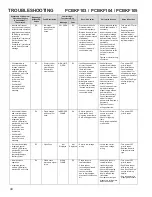
Page 43: ... icon illuminated ComfortNet thermostat scrolls Check Furnace message E0 Furnace lockout due to an excessive number of ignition retries 3 total LOCKOUT E0 Failure to establish fame Cause may be no gas to burners front cover pressure switch stuck open bad igniter or igniter alignment improper orifces or coated oxidized or improperly connected fame sensor Loss of fame after establishment Cause may b...

Page 44: ...for blockage Clean flters or remove obstruction Check circulator blower speed and performance Correct speed or replace blower motor if necessary Check burners for proper alignment Check fue and air inlet piping for blockage proper length elbows and termination Correct as necessary Check induced draft blower for proper performance Replace if necessary Tighten or correct wiring connection Turn power...

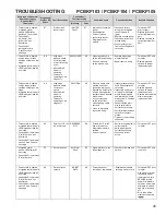
Page 45: ...cked fue and or inlet air pipe blocked drain system or weak induced draft blower Incorrect pressure switch set point or malfunctioning switch contacts Loose or improperly connected wiring Inspect pressure switch hose Repair replace if necessary Inspect fue and or inlet air piping for blockage proper length elbows and termination Check drain system Correct as necessary Check induced draft blower pe...

Page 46: ...s lost communications with circulator blower motor MOTOR COMM b1 Loose wiring connection at circulator motor control leads Failed circulator blower motor Failed integrated control module Tighten or correct wiring connection Check circulator blower motor Replace if necessary Check integrated control module Replace if necessary Turn power OFF prior to repair Replace circulator motor with correct rep...

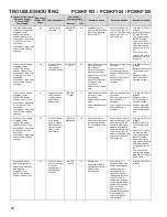
Page 47: ...Furnace message b7 MOTOR PARAMS b7 Furnace operates at reduced performance or Integrated control module LED display provides b9 error code b9 LOW ID AIRFLOW B9 Blocked filters Restrictive ductwork Undersized ductwork Check filters for blockage Clean filters or remove obstruction Check ductwork for blockage Remove obstruction Verify all registers are fully open Verify ductwork is appropriately size...

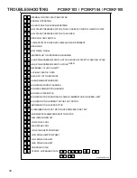
Page 48: ...OLARITY DATANOT YET ON NETWORK INVALID MEMORYCARD DATA BLOWER MOTOR NOT RUNNING BLOWER COMMUNICATION ERROR BLOWER HP MIS MATCH BLOWER MOTOR OPERATING IN POWER TEMPERATURE OR SPEED LIMIT BLOWER MOTOR CURRENT TRIP OR LOST ROTOR BLOWER MOTOR LOCKED ROTOR OVER UNDER VOLTAGE TRIP OR OVER TEMPERATURE TRIP INCOMPLETE PARAMETERS SENT TO MOTOR LOW INDOOR AIRFLOW LOW STAGE COOL HIGH STAGE COOL LOW STAGE GAS...

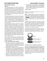
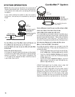
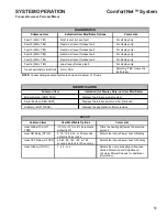
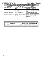
Page 49: ... 0 min the thermostat will display a cool heat call immediately regardless of the delay built into the outdoor unit control board This means the CTK03A or CTK04A could show COOL ON when the outdoor unit is still in a delay period The recommendation is to set up the compressor delay to at least 3 minutes 3 Dual Fuel When the CTK03A or CTK04A calls for gas heat the heat pump will shut off after a de...

Page 50: ...N FURNACE AND NON COMFORTNET COMPATIBLE SINGLE STAGE AIR CONDITIONER COMFORTNET SYSTEM ADVANCED FEATURES The ComfortNet system permits access to additional sys tem information advanced setup features and advanced di agnostic troubleshooting features These advanced features are organized into a menu structure The menus are ac cessed and navigated as described in the following section ACCESSING AND ...

Page 51: ...m of 3 times DIAGNOSTICS Submenu Item Indication for Display Only not User Modifiable Model Number MOD NUM Displays the furnace model number Serial Number SER NUM Displays the furnace serial number Optional Software SOFTWARE Displays the application software revision IDENTIFICATION Submenu Item User Modifiable Options Comments Heat Airflow Trim HT TRM 10 to 10 in 2 increments default is 0 Trims th...

Page 52: ...ng compatible single stage AC unit Cool ON Delay CL ON 5 10 20 or 30 seconds default is 5 seconds Selects the indoor blower ON delay for the non communicating compatible single stage AC unit Cool OFF Delay CL OFF 30 60 90 or 120 seconds default is 30 seconds Selects the indoor blower OFF delay for the non communicating compatible single stage AC unit NON COMM APPLIES ONLY TO A COMMUNICATING COMPAT...

Page 53: ...ges as described above Rapid Flashing x Normal network traffic x Control is talking on network as expected x None x None Green Receive LED On Solid x Data 1 Data 2 miss wire x Data 1 and data 2 wires reversed at furnace thermostat or CT compatible outdoor AC HP x Short between data 1 and data 2 wires x Short between data 1 or data 2 wires and R 24VAC or C 24VAC common x Check communications wiring...

Page 54: ... to identify any connected equipment The thermostat may identify one piece of equipment but not the other Broken or improper wiring is the most likely cause for the thermostat to fail to identify any equipment If an out door unit is not identified the thermostat will scroll CHECK SYSTEM indicating that no indoor unit was found ComfortNet System Wiring issues may be confirmed or eliminated by using...

Page 55: ...NDARY OF UNMARKED TRANSFORMERS VOLT OHM METER G ND PRIMARY SECONDARY TRANSFORMER R C METER READS 24 VOLTS LINE VOLTAGE NEUTRAL LINE VOLTAGE L1 HOT VOLT OHM METER METER READS 120 VOLTS VOLT OHM METER C R G ND N L1 VOLT OHM METER READS 96 VOLTS IN PHASE C R G ND N L1 VOLT OHM METER READS 144 VOLTS OUT OF PHASE If meter reads approximately 96 volts the primary to secondary are in phase if reads appro...

Page 56: ...staller for proper furnace operation Remember that dirty filters are the most common cause of inadequate heating or cooling performance Maintenance Improper filter maintenance is the most common cause of inadequate heating or cooling performance Filters should be cleaned permanent or replaced disposable every two months or as required It is the owner s responsibility to keep air filters clean When...

Page 57: ... Manometer to measure static pressure pressure drop across coils filters and draft 5 Water Manometer 12 to test gas inlet and mani fold pressure Other recording type instruments can be essential in solv ing abnormal problems however in many instances they may be rented from local sources Proper equipment promotes faster more efficient service and accurate repairs resulting in fewer call backs HEAT...

Page 58: ... capacity will be obtained With propane gas no unit gas valve regulator is used how ever the second stage supply line pressure regulator should be adjusted to give 11 water column with all other gas con suming appliances running The dissipation of the heat transferred to the heat exchanger is now controlled by the amount of air circulated over its surface The amount CFM of air circulated is govern...

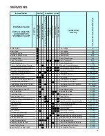
Page 59: ...ECKINGAUXILIARYLIMIT CONTROL 68 S 302 CHECKING FLAME ROLLOUT CONTROL 69 S 303 INDUCED DRAFT BLOWER MOTOR 70 S 304 CHECKING GAS VALVE REDUNDANT 70 S 305 CHECKING MAIN BURNERS 70 S 306 CHECKING ORIFICES 70 S 307 CHECKING GAS PRESSURE 71 S 308 CHECKING HOT SURFACE IGNITOR 74 S 309 CHECKING FOR FLASHBACK 74 S 310 CHECKING PRESSURE SWITCH 74 S 311 HIGH ALTITUDE APPLICATION USA 75 S 312 CHECKING FOR DEL...

Page 60: ... 160 400 20 45 90 180 360 900 46 78 157 391 21 43 86 171 343 857 47 19 38 76 153 383 22 41 82 164 327 818 48 75 150 375 23 39 78 157 313 783 49 147 367 24 37 75 150 300 750 50 18 36 72 144 360 25 36 72 144 288 720 51 141 355 26 34 69 138 277 692 52 69 138 346 27 33 67 133 265 667 53 17 34 136 340 28 32 64 129 257 643 54 67 133 333 29 31 62 124 248 621 55 131 327 30 30 60 120 240 600 56 16 32 64 12...

Page 61: ... Ignition Control Test Control S 313 Gas Valve or Gas Supply Shut Off Turn Valves to On Position S 317 Faulty Induced Draft Blower Test Induced Draft Motor S 303 Faulty Blower Motor PSC ECM Test Blower Motor PSC ECM S 16A B C Broken or Shorted Ignitor Test Ignitor S 308 Dirty Flame Sensor Low UA Clean Flame Sensor S 314 Stuck Gas Valve Replace Gas Valve S 304 Faulty Gas Valve Replace Gas Valve S 3...

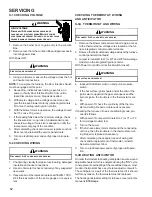
Page 62: ...ge or its equiva lent CHECKING THERMOSTAT WIRING AND ANTICIPATOR S 3A THERMOSTAT AND WIRING DISCONNECT ALL POWER BEFORE SERVICING WARNING 1 Remove the blower compartment door to gain access to the thermostat low voltage wires located at the fur nace integrated control module terminals 2 Remove the thermostat low voltage wires at the furnace control panel terminal board 3 Jumper terminals R to W or...

Page 63: ...lock switch 6 If line voltage is available to the primary side of trans former and not at secondary side the transformer is inoperative Replace 7 After completing check and or replacement of trans former and check and or repair of control circuit rein stall blower compartment door 8 Turn on electrical power and verify proper unit opera tion 6 Turn on electrical power and verify proper unit opera t...

Page 64: ...ry or death To use the diagnostic tool perform the following steps 1 Disconnect power to the furnace 2 Disconnect the 4 circuit control harness from the motor 3 Plug the 4 circuit connector from the diagnostic tool into the motor control connector 4 Connect one alligator clip from the diagnostic tool to a ground source 5 Connect the other alligator clip to a 24VAC source NOTE The alligator clips a...

Page 65: ...tage is present check supply voltage to the fur nace See section S 1 8 Disconnect power to the furnace Reconnect the 5 circuit power harness disconnected in step 2 Electrical Checks Low Voltage Control Circuits 1 Turn on power to the furnace WARNING Line Voltage now present 2 Check voltage between pins 1 and 4 on the 4 wire motor control harness between the motor and control board Voltage should b...

Page 66: ... winding is short circuited to the motor shell 5 Reassemble motor and control end bell in reverse of dis assembly Replace blower assembly into the furnace S 200 CHECKING DUCT STATIC The maximum and minimum allowable external static pres sures are found in the specification section These tables also show the amount of air being delivered at a given static by a given motor speed or pulley adjustment...

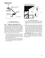
Page 67: ...e Ensure all registers are open and all duct dampers are in their final fully or partially open position 2 Place thermometers in the return and supply ducts as close to the furnace as possible Thermometers must not be influenced by radiant heat by being able to see the heat exchanger SUPPLY AIR RETURN AIR Checking Temperature Rise 3 Subtract the return air temperature from the supply air temperatu...

Page 68: ...as above replace the control VOLT OHM METER Testing Primary Limit Control 80 Furnaces 4 After completing check and or replacement of primary limit control reinstall burner compartment door 5 Turn on electrical power and verify proper unit opera tion To aid in identifying these controls refer to the Primary Limit Charts in furnace Technical Manual for part number temperature setting and color s cod...

Page 69: ...cause the control to open If the roll out control opens the air circulation blower will run continu ously On two stage models the ignition control the diagnostic light will flash 4 four times indicating a trip of the rollout switch These symptoms are identical to a trip of the primary limit control To aid in identifying these controls color coded labels have been affixed to the back of these contr...

Page 70: ...induced draft motor 6 After completing check and or replacement of in duced draft motor reinstall burner compartment door 7 Turn on electrical power and verify proper unit opera tion S 304 CHECKING GAS VALVE Redundant A combination redundant operator type gas valve which pro vides all manual and automatic control functions required for gas fired heating equipment is used The valve provides control...

Page 71: ... The line pressure supplied to the gas valve must be within the range specified below The supply pressure can be mea sured at the gas valve inlet pressure tap or at a hose fitting installed in the gas piping drip leg The supply pressure must be measured with the burners operating To measure the gas supply pressure use the following procedure WARNING DISCONNECT ELECTRICAL POWER AND SHUT OFF GAS SUP...

Page 72: ... 2 Connect a calibrated water manometer or appropriate gas pressure gauge at the gas valve outlet pressure tap Referto MeasuringGasPressure Two StageValves figure for two stage gas valve outlet pressure tap con nections LINE VOLTAGE NOW PRESENT WARNING 3 Turn ON the gas and electrical power supply and oper ate the furnace 4 White Rodgers 36G54 Valves a Back outlet pressure test screw inlet outlet ...

Page 73: ...ase pressure Replace regulator cover screw i Turn off all electrical power and gas supply to the sys tem j Remove the manometer hose from the hose barb fit ting or outlet pressure boss k Remove the 1 8 NPT hose barb fitting from the outlet pressure tap Replace the outlet pressure boss plug and seal with a high quality thread sealer WARNING HIGH VOLTAGE DISCONNECT ALL ELECTRICAL POWER AND SHUT OFF ...

Page 74: ...inction pop Since the end results of flashback and delayed ignition can be the same burning in the burner venturi a definite at tempt should be made to determine which has occurred If flashback should occur check for the following 1 Improper gas pressure adjust to proper pressure See S 307 CHECKING GAS PRESSURE 2 Check burner for proper alignment and or replace burner 3 Improper orifice size check...

Page 75: ...ng burning in the burner venturi If delayed ignition should occur the following should be checked 1 Improper gas pressure adjust to proper pressure See S 307 CHECKING GAS PRESSURE 2 Improper burner positioning burners should be in lo cating slots level front to rear and left to right 3 Carry over lighter tube or cross lighter obstructed clean 4 Main burner orifice s deformed or out of alignment to...

Page 76: ...ft blower high stage by measuring voltage between Pin 2 and Pin 4 on the 5 pin connector located on circuit board No voltage check for loose connection in the 5 pin con nector no call for high stage heat or replace ignition control 2 Y2 HUM O G Y1 C W1 R DE W2 1 4 If voltage is present in Steps 1 through 3 and the in duced draft blower is operating check for 120 volts to the ignitor during the pre...

Page 77: ...a heating cycle 3 As soon as flame is established a micro amp reading should be evident once proof of flame micro amp read ing is established the hot surface ignitor will be de energized 4 The Integrated Ignition controls will have 1 to 4 micro amps If the micro amp reading is less than the mini mum specified check for high resistance wiring con nections sensor to burner gap dirty flame sensor or ...

Page 78: ...P2 4 K1 OT NO Y P2 9 CALL FOR 2ND STAGE COMPRESSOR Y2 1 0K G FURN P2 1 C OT C C SECOND STAGE COMPRESSOR OUTPUT G CALL FOR EMERGENCY HEAT W1 FURN W2 HP F1 3A OT NC 24VAC 2ND STAGE COMPRESSOR DEMAND OUTPUT W1 CALL FOR FURNACE HEAT 6 8K G STAT VDC P3 4 F U R N A C E P2 6 K2 ODT OUTDOOR THERMOSTAT Y R SECOND STAGE FURNACE DEMAND OUTPUT MICROPROCESSOR Y2 HP P1 5 CALL FOR 2ND STAGE FURNACE HEAT O W2 CAL...

Page 79: ...SERVICING OR INSTALLING THIS UNIT MULTIPLE POWER SOURCES MAY BE PRESENT FAILURE TO DO SO MAY CAUSE PROPERTY DAMAGE PERSONAL INJURY OR DEATH DE HUMIDISTAT DEHUM1 2 Y2 HUM O G Y1 C W1 R DE W2 1 INTEGRATED IGNITION CONTROL ON 30 40 60 70 80 50 DE HUMIDISTAT GREEN WHITE BLACK ...

Page 80: ...TED CONTROL MODULE TRANSFORMER BK WH BK LOAD LINE WH 1 IGN N IGN W2 C EAC R 6 W1 W 2 DE Y1 R ANSI Z21 20 AUTOMATIC IGNITION SYSTEM 24VAC 60Hz 0 8 A MAX 15 12 GND 13 9 G TX 2 O G 1 59 4715 REV F Y2 7 W 1 3 W2 C IND LO 2 RX IND HI Y 1 Y1 O 1 G O DEHUM R R IND N HUM ST5 ST4 HUM C FS Y 2 1 DE HUM Y2 10 W 1 4 12V 2 Wiring is subject to change Always refer to the wiring diagram on the unit for the most ...

Page 81: ...CAUSE PROPERTY DAMAGE PERSONAL INJURY OR DEATH TYPICAL SCHEMATIC DM80VC AND DD80VC MODEL FURNACES PCBKF103 This schematic is for reference only Not all wiring is as shown above Refer to the appropriate wiring diagram for the unit being serviced Wiring is subject to change Always refer to the wiring diagram on the unit for the most up to date wiring ...

Page 82: ...NECT PU 3 IF ANY OF THE ORIGINAL WIRE AS SUPPLIED WITH THE FURNACE MUST BE REPLACED IT MUST BE REPLACED WITH WIRING MATERIAL HAVING A TEMPERATURE RATING OF C USE COPPER CONDUCTORS ONLY RD INTEGRATED CONTROL PROT DEVICE HIGH FIRE PRESSURE SWITCH W1 INTERNAL TO NO EQUIPMENT GND MVL 13 O SERVICING WIRING WH YL ID BLOWER TWO STAGE PRESSURE SWITCH ASSEMBLY 5 GND 5 BK IND HI IGN PK HLO 10 70kBTU 90kBTU ...

Reviews: