IM
1133-C
DIII-NET COMMUNICATION GATEWAY
10
www.DaikinApplied.com
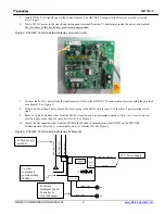
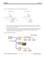
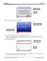
Figure 6, Incorporating DIII-NET board into an existing Modbus Daisy Chain
11.
Connect a pair of wires from the MCB to the Modbus Communication Port (X2M) on the DIII-NET Communication
Gateway. See Figure 5. (
There should be 2 pairs of modbus wires connected to the MCB at this point, unless there
were none to begin with, see Figure 6.)
12.
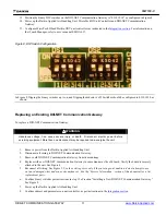
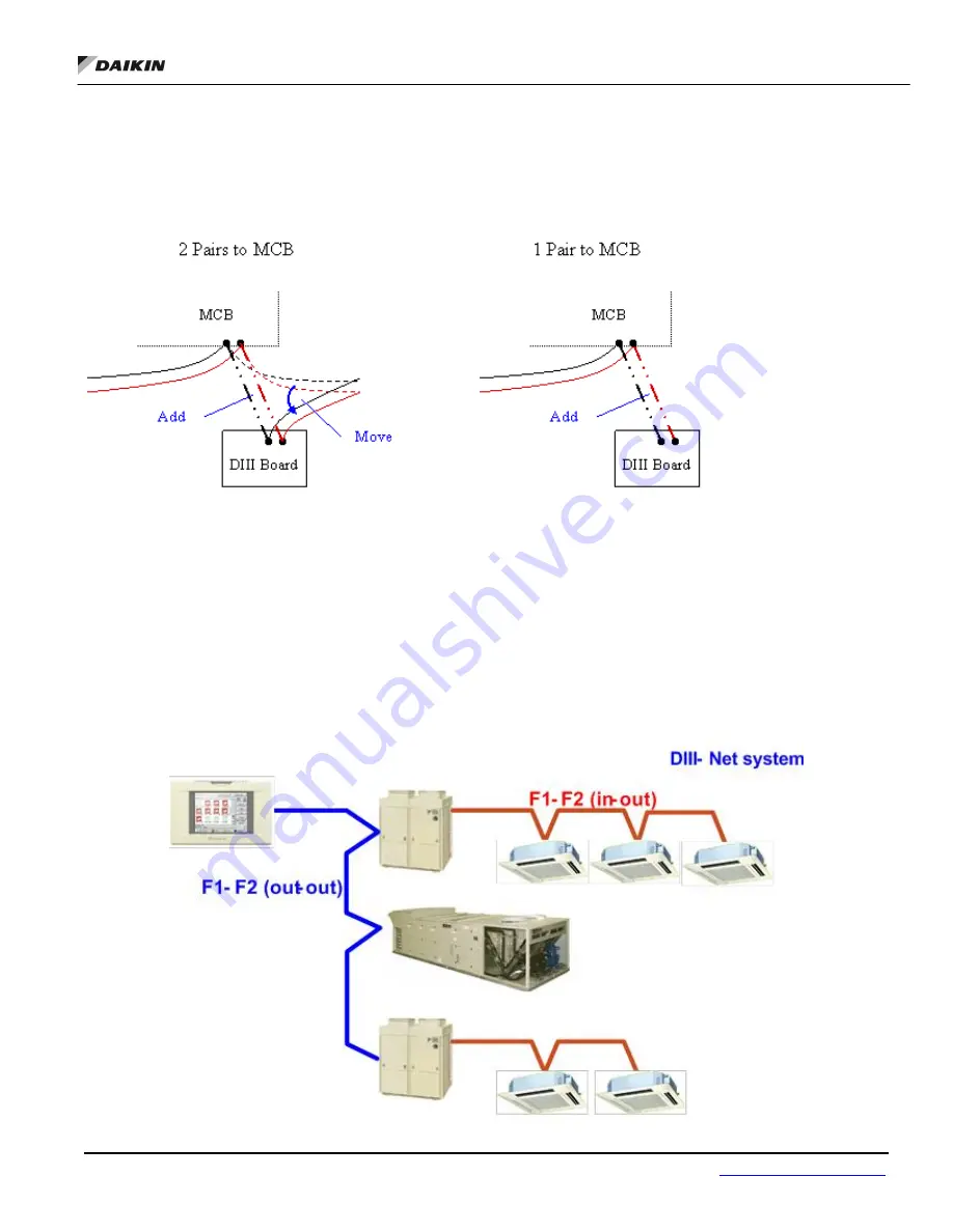
The DIII-NET Communications Gateway is treated like any other outdoor unit on the DIII-NET communications trunk.
Connect DIII-NET communication wires from the outdoor unit trunk to the DIII-NET communications port (X7A),
using the provided wire harness. See Figure 7.
Polarity does not matter. For more information on DIII-Net
communications wiring refer to Manual DCS601C71
Figure 7, DIII-NET Wiring Schematic


