IM
1133-C
DIII-NET COMMUNICATION GATEWAY
11
www.DaikinApplied.com
13.
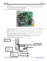
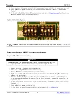
Position the binary DIP switches on the DIII-NET Communication Gateway to “0110 1010” as configured in Figure 8.
14.
Power up the Daikin Applied Air Handling Unit, MicroTech III Unit Controller and DIII-NET Communication
Gateway.
15.
Configure MicroTech III and Daikin VRV unit controllers as instructed in the
Integration section
. For information on
the iTouch Manager, refer to user’s manual EM11A017.
Figure 8, DIP Switch Configuration
In Figure 8, flipping the binary switches up is on, and flipping them down is off. Switches should be configured to 0110 1010 as
shown.
Replacing an Existing DIII-NET Communication Gateway
To replace a DIII-NET Communication Gateway:
!
WARNING
Hazardous voltage. Can cause severe injury or death. Disconnect electric power before
servicing equipment. More than one disconnect may be required to de-energize the unit.
1.
Remove power from the Daikin Applied Air Handling Unit.
2.
Disconnect all wiring to DIII-NET Communication Gateway.
3.
Remove old DIII-NET Communication Gateway from its mountings.
4.
Replace with new DIII-NET Communication Gateway in same manner as the old board. Verify the board is securely
attached to the unit. See Figure 4.
5.
Reconnect all wiring. See Figure 2.
Use the existing wires only if they are in good condition; do not attempt to use
worn or damaged wires under any circumstances. See the “Service Information” section of this document for a list
replacement parts.
6.
Confirm binary switches per instructions in step 13 of section “Installing a New DIII-NET Communication Gateway.”
See Figure 8.
7.
Power up the Daikin Applied Air Handling Unit.
8.
Confirm address and parameters on unit controller, as per instructions in the
Integration section
.


