


drm.daikinmalaysia.com |
3
Installation Instructions
Daikin Refrigeration Malaysia
January, 2021
Document Number: F-28184 | Ver. 1
ENGLISH
ENGLISH
WARNING
AC 24 V
To avoid injury and damage to persons and
devices, it is absolutely necessary these
instructions are carefully read and observed
prior to assembly and commissioning.
•
Do not remove the cover before the power
supply is fully switched off.
•
Switch off the power line before wiring the
actuator.
• Do not touch anything on the PCB.
• Connect via safety transformer.
•
Prior to assembly and maintenance work on
the system, must be:
–depressurized
–
cooled down
–emptied
–cleaned
Failure to comply may lead to equipment
damage or personal injury.
Necessary assembly, start-up, and maintenance
work must be performed only by qualified,
trained personnel.
Wire the actuator according to the wiring dia
-
gram.
Please comply with the instructions of the
system.
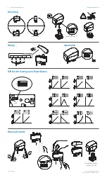
Mounting
The actuator should be mounted with the valve
stem in either horizontal position or pointing
upwards.
The actuator is fixed to the valve body by means
of a ribbed nut which requires no tools for
mounting. The ribbed nut should be tightened by
hand.
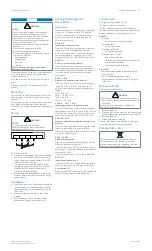
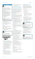
Wiring
WARNING
AC 24 V
• Connect via safety transformer.
Failure to comply can lead to equipment
damage or personal injury
MP 130-24MP-10M
24~
0-10V
0-20mA
24
0-10V
DKN-MP130-24MP
Red
Grey
Black
White
Auto sleep mode
a. If actuator is charged by 24 V supply voltage
and if it is not installed on PICV valve, it will
stop in lower position and switch off all LED
indicators after 5 minutes.
b. It is mandatory to drive the spindle of the
actuator to upper position before it will be
installed on PICV valve (please refer to
manual override drawings)!
c.
Auto sleep mode switches back to learning
mode by pressing RESET button or by cycling
power supply.
Installation
a. Check the valve neck. The actuator should be
in stem up position (factory setting). Ensure
that the actuator is mounted securely on the
valve body
b.
Wire the actuator according to the wiring
diagram.
c. The direction of stem movement can be
observed on the position indicator (1).
DIP Switch Settings and
Reset Button
DIP switches
Factory settings: ALL switches (4) (except SW 2
which is in ON position) are in OFF position!
NOTE:
All combinations of DIP switches are
allowed. All functions that are selected are
added consecutively.
SW 1: 0/2
Input signal range selector
If set to OFF position, the input signal is in the
range from 2-10 V (voltage input) or from
4-20 mA (current input). If set to ON position,
the input signal is in the range from 0-10 V
(voltage input) or from 0-20 mA (current input).
SW 2: D/I
Direct or inverse acting selector
If set to OFF position, the actuator is direct
acting (stem contracts as voltage increases). If
the actuator is set to ON position, the actuator
is inverse acting (stem extracts as voltage
increases).
SW 3: ---/Seq
Normal or sequential mode selector
If set to OFF position, the actuator is working in
range 0(2)-10 V or 0(4)-20 mA. If set to ON
position, the actuator is working in sequential
range:
0(2) … 5 (6) V or
(0(4) … 10 (12) mA) or
(5(6) … 10 V) or
(10(12) … 20 mA).
SW 4: 0 … 5 V/5 … 10 V
Input signal range in sequential mode
If set to OFF position, the actuator is working in
sequential range 0(2)-5 (6) V or 0(4)-10 (12) mA.
If set to ON position, the actuator is working in
sequential range; 5(6)-10 V or 10(12)-20 mA.
SW 5: LIN/LOG
Linear or equal percentage flow through valve
selector
If set to ON position, the flow through the valve
is equal percentage to the control signal.
If set to OFF position, the valve position is linear
acc. to the control signal.
SW 6: ---/ASTK
Anti-blocking function
Exercises the valve to avoid blocking in periods
when the heating/cooling is off.
If set to ON position (ASTK), the valve motion is
switched on. The actuator opens and closes the
valve every 7 days.
If set to OFF position (---), function is disabled.
SW 7: U/I
Input signal type selector
If set to OFF position, voltage input is selected.
If set to ON position, current input is selected.
Reset button (3)
Pressing the RESET-button for 2 sec. causes the
actuator to start self stroking procedure.
Function test
The light emitting diodes (LEDs)
(1) (green - direction indicator),
(2) (red - reset and normal mode indicator)
indicate whether the actuator is in operation the
operating status, and potentional failures.
Red LED:
• No light
–
no operation or no power supply
• Constant light
– normal operation
• Flashing light (1 Hz)
–
self-adjusting mode
• Flashing light (~ 3 Hz):
–
power supply too low
–
initial self-adjusting time too short due to
too short valve strokes
– failure during self calibration
Green LED:
• Spindle extracts (green led diode blinking
once per sec.)
• Spindle retracting (green LED on)
• Actuator reached set-point acc. to Y signal
(LED off).
Manual Override
(for service purposes only)
WARNING
Risk of Equipment Damage or Personal Injury
•
Do not manually operate the drive if power is
connected.
Failure to comply may lead to equipment
damage or personal injury.
a. Remove cover (1)
b. Press and hold the button (on the bottom side
of the actuator) (2) during manual override (3)
c. Replace cover (4)
d. Install actuator on valve (5)
Note: A ‘click’ sound is indicating that the gear
wheel has jumped into normal position.
Disposal Instruction
This product should be dismantled and its
components sorted if possible, in various
groups before recycling or disposal. Always
follow the local disposal regulations.


