SERVICING
40
S-311 High Altitude Application (USA)
The furnace as shipped requires no change to run between
0 - 7500 feet. Do not attempt to increase the firing rate
by changing orifices or increasing the manifold pressure
below 7500 feet. feet. This can cause poor combustion and
equipment failure. High altitude installations above 7500
feet. feet may require both a pressure switch and an orifice
change. These changes are necessary to compensate for
the natural reduction in the density of both the gasfuel and
the combustion air at higher altitude.
S-312 Checking For Delayed Ignition
Delayed ignition is a delay in lighting a combustible mixture
of gas and air which has accumulated in the combustion
chamber.
Furnace design makes this extremely unlikely unless safety
controls have been by-passed or tampered with. Never by-
pass or alter furnace controls.
If delayed ignition should occur, the following should be
checked:
1. Improper gas pressure - adjust to proper pressure.
2. Improper burner positioning - burners should be in locating
slots, level front to rear and left to right.
3. Carry over (lighter tube or cross lighter) obstructed - clean.
4. Main burner orifice(s) deformed, or out of alignment to
burner - replace.
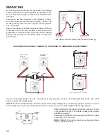
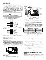
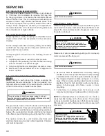
S-313 CHECKING INTEGRATED IGNITION CONTROL
BOARDS
NOTE:
Failure to earth ground the furnace, reversing the
neutral and hot wire connection to the line (polarity), or a
high resistance connection in the neutral line may cause the
control to lockout due to failure to sense flame.
T
O AVO
ID
THE
RI
SK OF ELECT
RI
CAL SHOCK,
WIRI
NG TO THE UN
I
T
MUST BE
PR
O
P
E
R
LY
P
OLA
RI
ZE
D
AN
D
G
R
OUN
D
E
D
.
D
I
SCONNECT
P
O
W
E
R
BEFO
R
E
P
E
R
FO
R
M
I
NG SE
R
V
I
CE L
I
STE
D
BELO
W
.
WARNING
The ground wire must run from the furnace all the way back
to the electrical panel. Proper grounding can be confirmed by
disconnecting the electrical power and measuring resistance
between the neutral (white) connection and the burner closest
to the flame sensor. Resistance should be less than 2 ohms.
The ignition control is a combination electronic and
electromechanical device and is not field repairable. Complete
unit must be replaced.
L
I
NE VOLTAGE NO
W
PR
ESENT
WARNING
S-314 Checking Flame Sensor
A flame sensing device is used in conjunction with the ignition
control module to prove combustion. If proof of flame is not
present the control will de-energize the gas valve and “retry”
for ignition or lockout.
WARNING
H
I
GH
VOLTAGE
D
I
SCONNECT
ALL
P
O
W
E
R
BEFO
R
E SE
R
V
I
C
I
NG O
R
I
NSTALL
I
NG TH
I
S UN
I
T.
M
ULT
IP
LE
P
O
W
E
R
SOU
R
CES MAY
BE
PR
ESENT.
F
A
I
LU
R
E TO
D
O SO MAY CAUSE
PR
O
P
E
R
TY
D
AMAGE,
P
E
R
SONAL
I
N
J
U
R
Y O
R
D
EATH.
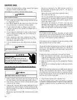
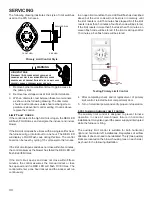
Flame current can be measured by putting a D.C. microamp
meter in series with the flame rod.
L
I
NE VOLTAGE NO
W
PR
ESENT
WARNING
3. As soon as flame is established a micro-amp reading
should be evident once proof of flame (micro-amp reading)
is established, the hot surface ignitor will be de-energized.
4. The Integrated Ignition controls will have 1 to 4 micro-
amps. If the micro-amp reading is less than the minimum
specified, check for high resistance wiring connections,
sensor to burner gap, dirty flame sensor, or poor
grounding.
5. If absolutely no reading, check for continuity on all
components and if good - replace ignition control module.
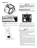
NOTE:
Contaminated fuel or combustion air can create a
nearly invisible coating on the flame sensor. This coating
works as an insulator causing a loss in the flame sense signal.
If this situation occurs the flame sensor must be cleaned with
steel wool.
WARNING
H
I
GH
VOLTAGE
D
I
SCONNECT
ALL
P
O
W
E
R
BEFO
R
E SE
R
V
I
C
I
NG O
R
I
NSTALL
I
NG TH
I
S UN
I
T.
M
ULT
IP
LE
P
O
W
E
R
SOU
R
CES MAY
BE
PR
ESENT.
F
A
I
LU
R
E TO
D
O SO MAY CAUSE
PR
O
P
E
R
TY
D
AMAGE,
P
E
R
SONAL
I
N
J
U
R
Y O
R
D
EATH.

