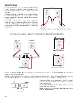
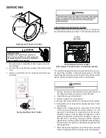
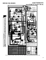
background image

WIRING DIAGRAMS

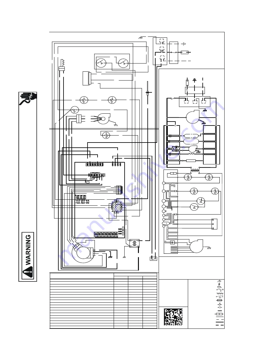
Wiring is subject to change.  Always refer to the wiring diagram on the unit for the most up-to-date wiring.

HI

G

H V

O

LT

A

G

E!

DI

SCO

NNE

CT

 AL

PO

W

ER BE

FO

RE

 S

ERV

ICI

NG

 O

R I

NS

TA

LL

IN

G

 T

HI

S

U

N

IT

.  M

U

LT

IPL

E PO

W

ER

 SO

U

R

C

ES M

AY B

E P

R

ESEN

T.

  F

A

IL

U

R

TO

DO

 S

O

 M

AY

 CAUS

E P

RO

PE

RT

Y DAM

AG

E,

 P

ERS

O

NAL

 INJ

UR

Y O

R DE

AT

H

.

43

GN

GND

RD

G

N

24

VA

C

11

5

VA

C

GND

G

RD

0140F02630-A

BK

EAC

HUMIDIFIER

ID

NEUTRAL

WIRING TO UNIT

L

IN

TE

G

RA

TE

D C

O

NT

RO

L M

O

DU

LE

HOT SURFACE

GND

BLWR

NEUTRAL

WARNING:

GROUNDED.

OVERCURRENT PROTECTION DEVICE

MUST BE PROPERLY

SWITCH

NEUTRAL

ELECTRONIC

AIR

IGN

IND HI

DISCONNECT

FS

POLARIZED AND

NEUTRAL

LINE

NEUTRAL

JUNCTION BOX

BLWR

IND LO

N

INDOOR

AIR CLEANER

HUM

DOOR

NEUTRAL

IN

TE

G

RA

TE

D C

O

NT

RO

L M

O

DU

LE

TO 115VAC/ 1Ø /60 HZ POWER SUPPLY WITH

115 VAC

HUM-OUT

IGNITER

CIRCULATOR

BEFORE SERVICING.

FLAME SENSOR

DISCONNECT POWER

LINE

GND

BR

W

H

G

Y

YL

O

R

PK

RD

W

H

BK

G

Y

LIMIT CONTROL

AUXILIARY

AUTO RESET

PK

WARNING:DISCONNECT

40

 V

A

TR

AN

SF

O

RM

ER

N

NO

G

C

SWITCH

PRESSURE

LOW FIRE

SENSOR

FLAME

1 ROLL OUT SWITCH

SOME UNITS MAY HAVE

C

TO UNIT MUST BE

PU

BK

AND GROUNDED.

1

JUNC
TIO

N B

O

X

W

H

3

BL

BR

W

H

NO

LIMIT CONTROL

AUTO RESET PRIMARY

WH

1

WH

L

RD

GY

BK

SWITCH ASSEMBLY

ID BLOWER TWO-STAGE PRESSURE

OR

SERVICING. WIRING

SWITCH

PRESSURE

HIGH FIRE

PK

RD

L

N

BK

C

DOOR OPEN)

(OPEN WHEN

DOOR SWITCH

COMPARTMENT

BLOWER

GND

1

BLOWER

CIRCULATOR

OR

Ø /60 HZ

DISCONNECT

(WHITE RODGERS)

GAS VALVE

TWO STAGE

OVERCURRENT

CONNECTOR

2 CIRCUIT

GND

WH

CHASSIS

GROUND

2

3

IGNITER

SURFACE

HOT

2

YL

PU

2

C

BLOWER

DRAFT

INDUCED

PM

BK

BLOWER COMPARTMENT

115 VAC/ 1

BK

ECM MTR

HARNESS

HI

O

R

POWER BEFORE

RD

BK

TO

POWER SUPPLY WITH

BURNER COMPARTMENT

PROTECTION DEVICE

PROPERLY POLARIZED

NOTES:

1. SET HEAT ANTICIPATOR ON ROOM THERMOSTAT AT 0.7 AMPS.

2. MANUFACTURER'S SPECIFIED REPLACEMENT PARTS MUST BE USED

    WHEN SERVICING.

3. IF ANY OF THE ORIGINAL WIRE AS SUPPLIED WITH THE FURNACE

MUST BE REPLACED IT MUST BE REPLACED WITH  WIRING MATERIAL 

HAVING A TEMPERATURE RATING OF AT LEAST 105  C. USE COPPER 

CONDUCTORS ONLY.

4. UNIT MUST BE PERMANENTLY GROUNDED AND CONFORM TO N.E.C. 

    AND LOCAL CODES.

5. TO RECALL THE LAST 6 FAULTS, MOST RECENT TO LEAST RECENT, 

    DEPRESS SWITCH FOR MORE THAN 2 SECONDS WHILE IN STANDBY

    (NO THERMOSTAT INPUTS)

COLOR CODES:

PK PINK

BR BROWN

WH WHITE

BL BLUE

GY GRAY

RD RED

YL YELLOW

OR ORANGE

PU  PURPLE

GN GREEN

BK BLACK

1

2

3

4

5

6

7

8

9

10

11

12

READ CODES FROM LEFT TO RIGHT

EA

C-H

XF

M

R-H

CIRC

-H

LIN

E-H

E2

0

E3

9

E2

E1

E1

5

E8

E5

E4

E3

E7

E6

E25

5

E26

W14

HUM-H K8

1

LE

FT

CE

NT

ER

RI

G

HT

SW3

3

1

3

1

3

SW1

R223

SW2

6

R226

TW

IN

DE

HU

M

24

HU

M

E21

E34

E24

W2 W/W1 R

G

R

Y/Y1 Y2

RD

BL

RD

BR

BR

BK

BK

BK

W

H

W

H

W

H

W

H

RD

BK

YL

G

Y

W

H

O

R

G

N

PU

PU

PU

PU

NE

UT

2

NE

UT

1

CIRC

-N

EA

C-N

HU

M

-N

XF

M

R-N

LIN

E-N

GND

MICRO

TO

PS2 (9)

TR (7)

G

C

C

TH (3)

24

V T

HE

RM

O

ST

AT

 C

O

NN

EC

TIO

NS


N.E

.C

. C

LA

SS

 2 W

IR

E

VALVE

GAS

W2

TRANSFORMER

HLI (8)

Y2

Y1

RLO (6)

O

MVL (10)

NO

W1

HI

R

MANUAL RESET ROLLOUT LIMIT SWITCH

HIGH FIRE

PRESS. SWTICH.

C

LOW FIRE PRESS

SWITCH

MVH (4)

DEHUM

PS1(5)

AUTO RESET

PRIMARY LIMIT

24 VAC

NO

PM

MVC (11)

C

BLWR

AIR

INDOOR

CIRCULATOR

R

TO

MICRO

TO

TO

+VDC

40 VA

INTERGRATED CONTROL MODULE

RLI (12)

AUTO RESET AUX LIMIT

HLO (1)

Internal Faults or IRQ Loss

E

E

E

Lockout Due to Excessive Retries Recycle

E

E

0

Low Stage Pressure Switch Stuck Closed

E

E

1

Low Stage pressure Switch Open

E

E

2

Open High Limit Switch

E

E

3

Flame Detected When no Flame Should be

E

E

4

Open Fuse

E

E

5

Low Flame Signal

E

E

6

Ignitor Relay Fault

E

E

L

High Stage Pressure Switch Stuck Closed

E

E

8

High Stage Pressure Switch Open

E

E

9

Reversed Line Polarity or Grounding Error

E

E

A

Internal Gas Valve Error

E

E

b

External Gas Valve Error

E

E

C

Open Rollout Switch

E

1

1

ignitor Open

E

E

N

Inducer Relay Error

E

E

j

Twin Error

E

E

H

Grounding Error

E

1

0

Seven Segment Display

Status

Seg#3

Seg#2

Seg#1

5

3

4

1 2

RD

BK

OR

BL

YL

RD

BL

OR

BK

YL

T1

T2
T3
T4
T5
COM

RD

SWITCH (PRESS.)

FIELD SPLICE

FIELD GND

EQUIPMENT GND

       INTERNAL TO

PROT. DEVICE

INTEGRATED CONTROL

PLUG CONNECTION

SWITCH (TEMP.)

JUNCTION

LOW VOLTAGE (24V)

 OVERCURRENT

TERMINAL

IGNITER

LOW VOLTAGE FIELD

HI VOLTAGE (115V)

HI VOLTAGE FIELD

DC80TN/DM80TN

(with PCBBF161 Control Board)

Summary of Contents for DM80TN

Page 1: ...ROPRIATE SERVICE MANUAL BEFORE BEGINNING REPAIRS Only personnel that have been trained to install adjust service or repair hereinafter service the equipment specified in this manual should service the...

Page 2: ...after servicing WARNING FIRE EXPLOSION OR CARBON MONOXIDE POISONING HAZARD Failure to replace with proper control could result in fire explosion or carbon monoxide poisoning This appliance uses NEGATI...

Page 3: ...ational Fuel Gas Code ANSI Z223 1 WARNING If not installed operated and maintained in accordance with the manufacturer s instructions this product could expose you to substances during fuel combustion...

Page 4: ...259 216 El mon xido de carbono puede causar enfermedades severas como da o cerebral permanente muerte Las emisiones de mon xido de carbono pueden circular a trav s del aparato cuando se opera en cualq...

Page 5: ...Initial Release B 1st Revision Configuration M Upflow Horizontal Major Revision C Downflow Horizontal A Initial Release B 1st Revision Nox AFUE 80 80 AFUE 92 92 AFUE 96 96 AFUE 97 97 AFUE Cabinet Widt...

Page 6: ...d in accordance with local codes or in their absence with the latest edition of The National Electric Code ANSI NFPA 70 and or The Canadian Electric Code CSA C22 1 An electrical disconnect must be pro...

Page 7: ...to high fire 1 Auto 2 Fixed Time Press the Left or Right menu switches to get to the A H S menu The menu will display these options no 10 20 30 60 AUt Fixed time options are expressed in minutes on t...

Page 8: ...ating mounting grounding and controlling these accessories Accessory wiring connections are to be made through the 1 4 quick connect terminals provided on the furnace integrated control module The hum...

Page 9: ...blower is energized When the thermostat is satisfied The gas valve is de energized The inducer remains energized for the post purge period 15 seconds The indoor blower runs for the selected off delay...

Page 10: ...r the thermostat is satisfied the compressor is de energized and the Cool Mode Fan Off Delay period begins Following the Cool Mode Fan Off Delay period the cool circulator and air cleaner relay are de...

Page 11: ...ACE BEFORE CHANGING SPEED TAPS WARNING CIRCULATING AIR AND FILTERS DUCTWORK AIR FLOW Duct systems and register sizes must be properly designed for the C F M and external static pressure rating of the...

Page 12: ...500 1459 1419 1387 1349 1317 1286 F01 1036 985 940 895 848 799 751 705 F02 1391 1352 1314 1278 1241 1209 1175 1140 F03 710 646 580 515 432 367 314 274 F04 1138 1091 1045 1001 959 920 876 832 F05 1209...

Page 13: ...156 1103 1037 982 932 878 F05 1811 1769 1730 1686 1649 1610 1572 1525 F06 1541 1487 1440 1395 1353 1310 1251 1203 F07 1587 1545 1494 1451 1409 1367 1316 1266 F08 1703 1659 1613 1579 1537 1495 1451 140...

Page 14: ...544 1500 1459 1419 1387 1349 1317 1286 F01 1036 985 940 895 848 799 751 705 F02 1391 1352 1314 1278 1241 1209 1175 1140 F03 710 646 580 515 432 367 314 274 F04 1138 1091 1045 1001 959 920 876 832 F05...

Page 15: ...07 1156 1103 1037 982 932 878 F05 1811 1769 1730 1686 1649 1610 1572 1525 F06 1541 1487 1440 1395 1353 1310 1251 1203 F07 1587 1545 1494 1451 1409 1367 1316 1266 F08 1703 1659 1613 1579 1537 1495 1451...

Page 16: ...19 1387 1349 1317 1286 F01 1036 985 940 895 848 799 751 705 F02 1391 1352 1314 1278 1241 1209 1175 1140 F03 710 646 580 515 432 367 314 274 F04 1138 1091 1045 1001 959 920 876 832 F05 1209 1166 1124 1...

Page 17: ...294 F04 1260 1207 1156 1103 1037 982 932 878 F05 1811 1769 1730 1686 1649 1610 1572 1525 F06 1541 1487 1440 1395 1353 1310 1251 1203 F07 1587 1545 1494 1451 1409 1367 1316 1266 F08 1703 1659 1613 1579...

Page 18: ...4 928 F05 1588 37 1539 39 1494 40 1447 41 1401 42 1358 1313 1267 F01 1420 29 1359 31 1301 32 1254 33 1206 34 1152 1100 1044 F03 826 N A 744 N A 661 N A 573 N A 485 N A 399 339 N A F04 1623 N A 1567 N...

Page 19: ...60 F01 1176 1105 1020 935 864 797 729 673 F02 1513 1459 1400 1335 1253 1182 1122 1067 F03 1022 813 674 585 511 431 334 282 F04 1640 1595 1540 1489 1436 1367 1307 1254 F05 1843 1786 1747 1690 1643 1575...

Page 20: ...96 1160 F01 1176 1105 1020 935 864 797 729 673 F02 1513 1459 1400 1335 1253 1182 1122 1067 F03 1022 813 674 585 511 431 334 282 F04 1640 1595 1540 1489 1436 1367 1307 1254 F05 1843 1786 1747 1690 1643...

Page 21: ...302 1267 1232 1196 1160 F01 1176 1105 1020 935 864 797 729 673 F02 1513 1459 1400 1335 1253 1182 1122 1067 F03 1022 813 674 585 511 431 334 282 F04 1640 1595 1540 1489 1436 1367 1307 1254 F05 1843 178...

Page 22: ...N A 636 N A F04 1309 32 1261 33 1218 34 F02 1393 43 1348 44 1308 45 F04 1309 45 1261 47 1218 49 F05 1459 41 1414 42 1371 43 F01 1176 35 1105 38 1020 41 F03 1022 N A 813 N A 674 N A F04 1640 N A 1595...

Page 23: ...N A 402 349 300 F04 1182 35 1142 36 1103 1064 1025 F02 1270 47 1230 48 1196 1158 1123 F04 1182 50 1142 52 1103 1064 1025 F05 1336 44 1297 46 1264 1229 1193 F01 935 44 864 48 797 729 673 F03 585 N A 5...

Page 24: ...in 7 Secs increments from 0 to 35 Secs Cool Off Delay Delay Seconds Default set at 65 Secs Adjustments can be made in 5 Secs increments from 0 to 120 Secs Blower Speed for 1st Stage Gas Heat Mode xx...

Page 25: ...SYSTEM OPERATION 25 2 Stage Status Codes Status Menu Idle Continous Fan Compressor Cooling Low Stage Compressor Cooling High Stage Gas heat Low Stage Gas heat High Stage OEM test Mode Mode Main Menu...

Page 26: ...CAL COMPONENTS ARE CONTAINED IN BOTH COMPARTMENTS TO AVOID ELECTRICAL SHOCK INJURY OR DEATH DO NOT REMOVE ANY INTERNAL COMPARTMENT COVERS OR ATTEMPT ANY ADJUSTMENT CONTACT A QUALIFIED SERVICE AGENT AT...

Page 27: ...2 164 327 655 1636 37 97 195 486 12 75 150 300 600 1500 38 23 47 95 189 474 13 69 138 277 555 1385 39 92 185 462 14 64 129 257 514 1286 40 22 45 90 180 450 15 60 120 240 480 1200 41 176 439 16 56 113...

Page 28: ...he gas valve turn downward clockwise to increase pressure and input and upward counterclockwise to decrease pressure and input A properly operating unit must have the BTU per hour input and CFM of air...

Page 29: ...king Auxiliary Limit Control 34 S 302 Checking Flame Rollout Control 35 S 303 Induced Draft Blower Motor 36 S 304 Checking Gas Valve Redundant 36 S 305 Checking Main Burners 36 S 306 Checking Orifices...

Page 30: ...tely 144 volts out of phase reverse low voltage wires NOTE For flame rectification the common side of the secondary voltage 24 V is cabinet grounded If you were to bench test a transformer the primary...

Page 31: ...king Thermostat And Wiring DISCONNECT ALL POWER BEFORE SERVICING WARNING 1 Remove the blower compartment door to gain access to the thermostat low voltage wires located at the furnace integrated contr...

Page 32: ...T1 T5 wires on the control board Green ground wire connected to cabinet ground The control harness has The nine speed ECM motor requires a line voltage power supply black connected to CIRC H and white...

Page 33: ...urnace as possible Thermometers must not be influenced by radiant heat by being able to see the heat exchanger SUPPLY AIR RETURN AIR Checking Temperature Rise 3 Subtract the return air temperature fro...

Page 34: ...sh ELEVEN times If the limit circuit opens and does not close within fifteen minutes the control assumes the manual rollout or fuse has opened and the RED LED will flash FIVE times The control will en...

Page 35: ...ut occur An over firing condition or flame impingement on the heat shield may also cause the control to open If the rollout control opens the air circulation blower will run continuously 1 Remove the...

Page 36: ...s used The valve provides control of main burner gas flow pressure regulation and 100 percent safety shut off Two stage gas valves always require 24 volts between common and low fire main coil to open...

Page 37: ...e Rodgers Model 36J54 Connected to Manometer 3 5 White Rodgers Model 36J54 Connected to Manometer 1 Turn OFF gas to furnace at the manual gas shutoff valve external to the furnace 2 Connect a calibrat...

Page 38: ...outlet pressure tap White Rodgers 36J54 valve Turn outlet pressure test screw in to seal pressure port clockwise 7 in lb mini mum 14 Turn on electrical power and gas supply to the system 15 Close the...

Page 39: ...r at the moment of ignition after a burner heats up or when the burner turns off The latter is known as extinction pop Since the end results of flashback and delayed ignition can be the same burning i...

Page 40: ...e electrical panel Proper grounding can be confirmed by disconnecting the electrical power and measuring resistance between the neutral white connection and the burner closest to the flame sensor Resi...

Page 41: ...t Correct short at flame sensor or in flame sensor wiring Short to ground in flame sense circuit Lingering burner flame Slow closing gas valve Open fuse Replace fuse Short in low voltage wiring Locate...

Page 42: ...ated control board Furnace fails to operate No 115 power to furnace or no 24 volt power to integrated control module Restore high voltage power to furnace and integrated control module Blown fuse or t...

Page 43: ...G OF AT LEAST 105 C USE COPPER CONDUCTORS ONLY 4 UNIT MUST BE PERMANENTLY GROUNDED AND CONFORM TO N E C AND LOCAL CODES 5 TO RECALL THE LAST 6 FAULTS MOST RECENT TO LEAST RECENT DEPRESS SWITCH FOR MOR...

Page 44: ...EEDBACK Daikin is very interested in all product comments Please fill out the feedback form on the following link https daikincomfort com contact us You can also scan the QR code on the right to be di...

Reviews: