background image

PRODUCT DESIGN

37

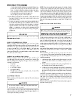
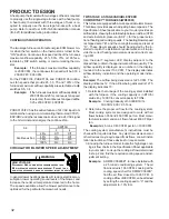
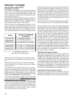
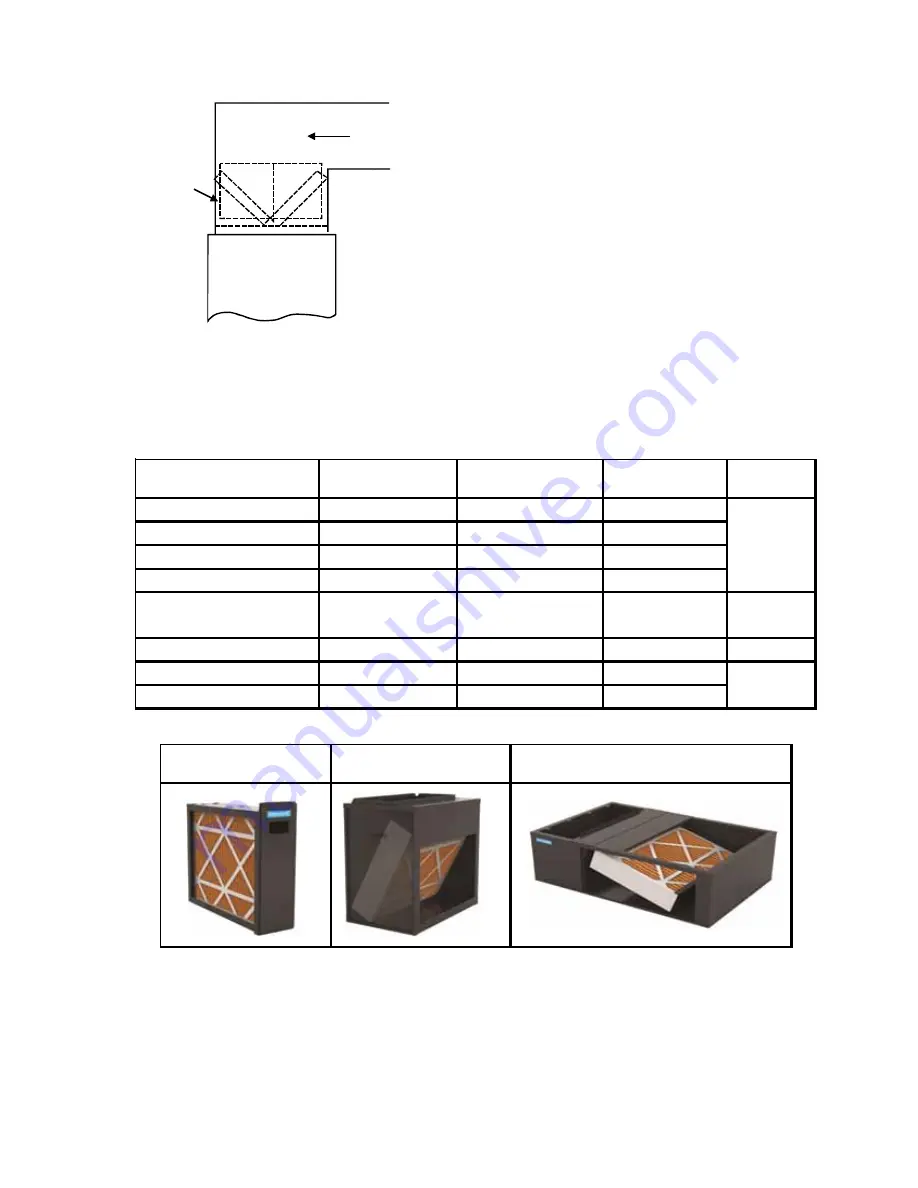
"A"
Min

Return Air

Optional

Access

Door

Horizontal Installations

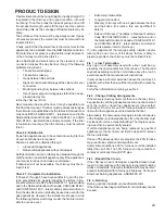
Filter(s) must be installed external to the furnace casing for
horizontal installations. For most installations it is prefer-
able to use a central return with filters installed in the duct
behind the return air grill. In this way filter replacement is
relatively simple by merely removing the grille, rather than
going into the attic or crawl space.

ADDITIONAL FILTERING ACCESSORIES

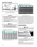
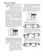
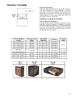
External Filter Rack Kit (EFR01)

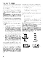
The external filter rack kit is intended to provide a location
external to the furnace casing, for installation of a perma-
nent filter on upflow model furnaces. The rack is designed to
mount over the indoor blower compartment area of either
side panel, and provide filter retention as well as a location
for attaching return air ductwork.

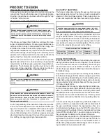
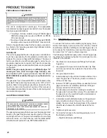
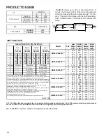
Air Cleaner Installation 

Location

Maximum Heating 

Airflow

Filter (Media) 

Dimensions

Part Number

Air Cleaner 

Family

Si de or bottom return

1200 CFM

16 i n X 20 i n x 5¼"

AM11-1620-5

Si de or bottom return

1600 CFM

16 i n X 25 i n x 5¼"

AM11-1625-5

Si de or bottom return

1600 CFM

20 i n X 20 i n x 5¼"

AM11-2020-5

Si de or bottom return

2000 CFM

20 i n X 25 i n x 5¼"

AM11-2025-5

Si de return

(for 2 s epa rate returns )

Si de return (Ri ght a ngl e)

2000 CFM

20 i n X 25 i n x 5¼"

AM11-2025-5RA

AM11-5RA

Bottom return (pl a tform)

2000 CFM

20 i n X 25 i n x 5¼"

AM11-2832-5PP

Bottom return (pl a tform)

2000 CFM

20 i n X 25 i n x 5¼"

AM11-2843-5PP

AM11-5

2 X 1600 CFM

2, 16 i n X 25 i n x 5¼"

AM11-3225-5

AM11-3225

AM11-5PP

AM11-5

Family

AM11-5RA

Family

AM11-5PP

Family

Summary of Contents for DM80VC

Page 1: ...is to be used by qualified professionally trained HVAC technicians only Daikin does not assume any responsibility for property damage or personal injury due to improper service procedures or services...

Page 2: ...INJURY OR DEATH IMPORTANTINFORMATION 3 4 PRODUCTIDENTIFICATION 5 9 ACCESSORIES 10 OPERATINGINSTRUCTIONS 11 13 PRODUCT DESIGN 14 37 SYSTEM OPERATION 38 42 TROUBLESHOOTING 43 48 SYSTEM OPERATION COMFOR...

Page 3: ...r assistance please contact CONSUMER INFORMATION LINE DAIKIN BRAND PRODUCTS TOLL FREE 1 877 254 4729 U S only email us at customerservice daikincomfort com fax us at 713 856 1821 Not a technical assis...

Page 4: ...omo da o cerebral permanente muerte Las emisiones de mon xido de carbono pueden circular a trav s del aparato cuando se opera en cualquier modo B10259 216 RISQUE D EMPOISONNEMENT AU MONOXYDE DE CARBON...

Page 5: ...al Release B 1st Revision Configuration M Upflow Horizontal Major Revision C Downflow Horizontal A Initial Release K Dedicated Upflow B 1st Revision D Dedicated Downflow Nox AFUE N Natural Gas 97 97 A...

Page 6: ...an integrated electronic ignition control and stainless steel tubular heat exchanger NOx certified Chassis sizes are now 17 5 and 21 wide DM80VC DM80VC0604B DM80VC0805C DM80VC1005C Daikin Brand 80 va...

Page 7: ...ub base terminal blocks 2 installation manual and homeowner guide CTK02 CTK02 Communicating Thermostat Kit Digitally communicating thermostat a necessary part of any communicating system Designed for...

Page 8: ...as furnace models This kit is intended to provide a location external to the furnace casing for installation of a permanent filter The rack is mounted over the indoor air blower compartment area of ei...

Page 9: ...06 N A LP Conversion Kit For use with Daikin Brand 2 stage Hydrid models or 2 stage variable speed models using a White Rodgers 36G54 2 stage gas valve kit or a Honeywell VR9205 2 stage gas valve kit...

Page 10: ...ER AFE180 60A EFR01 SBT17 SBT21 CTK0 LPM06 LPLP03 HA 02 DEHUM1 Description Dual Fuel Board EFR External Filter Rack Downflow Subbase 17 5 Downflow Subbase 21 Communicating Thermostat Propane Gas Conve...

Page 11: ...If the gas control switch or knob D Do not use this appliance if any part has been under water Immediately call a qualified service technician to inspect the appliance and to replace any part of the c...

Page 12: ...l eau Si cela se produit demandez immediatement a un reparateur qualifie d inspecter l appareil et de remplacer toute piece du systeme de controle et toute commande de gaz ayant ete dans l eau 0140F00...

Page 13: ...13 DU GAZ ARRIVEE INLET GAS IN ON POS LEVER SHOWN MANUAL GAS ON MARCHE MANUEL EN POS ROBINET A GAZ OPERATING INSTRUCTIONS...

Page 14: ...re removing a new control from its container Follow Steps 1 through 3 if installing the control on a furnace Return any old or new controls to their containers before touching any ungrounded object Pr...

Page 15: ...for installation details NOTE A subbase will not be required if an air conditioning coil is located beneath the furnace between the supply air opening and the combustible floor Exposure to contaminate...

Page 16: ...d other spaces of the building Turn on clothes dryers and any appliance not connected to the venting system Turn on any exhaust fans such as range hoods and bathroom exhausts so they shall operate at...

Page 17: ...3 or 7 4 or applicable provisions of the local building codes for deter mining the combustion air requirements for the appliances Most homes will require outside air be supplied to the fur nace area b...

Page 18: ...are connected by one or more openings in doors or floors having a total minimum free area of 2 in 2 1000 Btu hr 4400 mm2 kW of total input rating of all appliances 9 3 3 Outdoor Combustion Air Outdoo...

Page 19: ...Engineered combustion air installa tions shall provide an adequate supply of combustion ventilation and dilution air and shall be approved by the authority having jurisdiction 9 3 6 Mechanical Combus...

Page 20: ...TE The vertical height of the Category I venting system must be at least as great as the horizontal length of the venting system WARNING TO PREVENT POSSIBLE DEATH OR PERSONAL INJURY DUE TO ASPHYXIATIO...

Page 21: ...ubject which is currently available Proper Chimney Termination Check 1 Line terminate with listed vent cap Fix 1 No Yes Chimney channel free of solid and liquid fuel appliances Check 2 Change venting...

Page 22: ...the upper edge of the cleanout cover is at least 12 inches below the lower edge of the lowest chimney inlet opening A chimney without a cleanout could become partially blocked by debris If no cleanout...

Page 23: ...then the clay tile liner can probably be used as a vent for the gas appliances However the installer must keep in mind the following factors which may render the tile liner unsuit able for use as a ve...

Page 24: ...xible liners specifically intended and tested for gas applications are listed in the UL Gas and Oil Equipment Directory UL Standard 1777 For sizing of flexible liners see Note 22 and the tables in the...

Page 25: ...ng and gas types The furnace must be equipped to operate on the type of gas applied This includes any con version kits required for alternate fuels and or high altitude CAUTION TO PREVENT UNRELIABLE O...

Page 26: ...ly with local codes or in their absence with the latest edition of the National Fuel Gas Code NFPA 54 ANSI Z223 1 Length of Nominal Black Pipe Size Pipe in Feet 1 2 3 4 1 1 1 4 1 1 2 10 132 278 520 10...

Page 27: ...TE Never exceed specified pressures for testing Higher pressure may damage the gas valve and cause subsequent overfiring resulting in heat exchanger failure Disconnect this unit and shutoff valve from...

Page 28: ...tor must consider proper tank sizing safety efficiency ground char acteristics and aesthetics For a residential customer the size may range from 100 1 000 gallons depending on house hold use Typically...

Page 29: ...Any replacement wiring must be copper conductor 115VOLTLINECONNECTIONS Before proceeding with electrical connections ensure that the supply voltage frequency and phase correspond to that specified on...

Page 30: ...removal or rou tine maintenance A 40 V A transformer and an integrated electronic control are built into the furnace to allow use with most cooling equipment Consult the wiring diagram located in the...

Page 31: ...ssil fuel application A fossil fuel application is where an outdoor temperature sensor determines the most cost efficient means of heating heat pump gas furnace or both Y Two Stage Heating with Single...

Page 32: ...is blower provides ease in adjusting blower speeds The Specification Sheet applicable to your model provides an airflow table showing the relationship between airflow CFM and external static pressure...

Page 33: ...selection DIP switches on the integrated control module Select the desired cool ing speed tap by positioning switches 1 and 2 appro priately Select the desired adjust tap by positioning switches 3 and...

Page 34: ...profile see profiles above Set dip switches S4 1 and S4 2 to the appropriate ON OFF positions Dehumidification To enable set switch S5 1 to ON Cooling airflow will be reduced to 85 of nominal value d...

Page 35: ...Off On D On On Add 5 Off Off Minus 5 On Off Add 10 Off On Minus 10 On On A Off Off B On Off C Off On D On On A Off Off B On Off C Off On D On On Disabled Off Enabled On Disabled Off Enabled On 25 Off...

Page 36: ...r chamber When the furnace is used in connection with a cooling unit the furnace should be installed in parallel with or on the up stream side of the cooling unit to avoid condensation in the heating...

Page 37: ...d to mount over the indoor blower compartment area of either side panel and provide filter retention as well as a location for attaching return air ductwork Air Cleaner Installation Location Maximum H...

Page 38: ...at changes the call from high heat to low heat the control will immediately switch the induced draft blower and gas valve to their low stage settings The circulator blower will remain on high heating...

Page 39: ...g and dehumidistat call for dehumidification 7 Humidistat opens on humidity fall allowing furnace cir culator blower to switch back to normal cooling speed 8 R and Y1 G or Y1 Y2 G thermostat contacts...

Page 40: ...stic error code for this condition is E4 The probable causes are either a short to ground in flame sense circuit miswiring lingering burner flame or a slow closing gas valve 7 Open Fuse If the control...

Page 41: ...on is b3 Power Limit In attempting to deliver the airflow demand the motor may exceed its rated output power The mo tor will reduce its output to prevent exceeding its power limit This will result in...

Page 42: ...emand 22 Motor Parameters This condition occurs if the motor does not receive all the information is requires to oper ate or an event occurs that prevents the motor from run ning or the motor fails to...

Page 43: ...icon illuminated ComfortNet thermostat scrolls Check Furnace message E0 Furnace lockout due to an excessive number of ignition retries 3 total LOCKOUT E0 Failure to establish fame Cause may be no gas...

Page 44: ...or blockage Clean flters or remove obstruction Check circulator blower speed and performance Correct speed or replace blower motor if necessary Check burners for proper alignment Check fue and air inl...

Page 45: ...ked fue and or inlet air pipe blocked drain system or weak induced draft blower Incorrect pressure switch set point or malfunctioning switch contacts Loose or improperly connected wiring Inspect press...

Page 46: ...lost communications with circulator blower motor MOTOR COMM b1 Loose wiring connection at circulator motor control leads Failed circulator blower motor Failed integrated control module Tighten or cor...

Page 47: ...urnace message b7 MOTOR PARAMS b7 Furnace operates at reduced performance or Integrated control module LED display provides b9 error code b9 LOW ID AIRFLOW B9 Blocked filters Restrictive ductwork Unde...

Page 48: ...LARITY DATANOT YET ON NETWORK INVALID MEMORYCARD DATA BLOWER MOTOR NOT RUNNING BLOWER COMMUNICATION ERROR BLOWER HP MIS MATCH BLOWER MOTOR OPERATING IN POWER TEMPERATURE OR SPEED LIMIT BLOWER MOTOR CU...

Page 49: ...0 min the thermostat will display a cool heat call immediately regardless of the delay built into the outdoor unit control board This means the CTK03A or CTK04A could show COOL ON when the outdoor uni...

Page 50: ...FURNACE AND NON COMFORTNET COMPATIBLE SINGLE STAGE AIR CONDITIONER COMFORTNET SYSTEM ADVANCED FEATURES The ComfortNet system permits access to additional sys tem information advanced setup features a...

Page 51: ...of 3 times DIAGNOSTICS Submenu Item Indication for Display Only not User Modifiable Model Number MOD NUM Displays the furnace model number Serial Number SER NUM Displays the furnace serial number Opt...

Page 52: ...g compatible single stage AC unit Cool ON Delay CL ON 5 10 20 or 30 seconds default is 5 seconds Selects the indoor blower ON delay for the non communicating compatible single stage AC unit Cool OFF D...

Page 53: ...es as described above Rapid Flashing x Normal network traffic x Control is talking on network as expected x None x None Green Receive LED On Solid x Data 1 Data 2 miss wire x Data 1 and data 2 wires r...

Page 54: ...to identify any connected equipment The thermostat may identify one piece of equipment but not the other Broken or improper wiring is the most likely cause for the thermostat to fail to identify any e...

Page 55: ...DARY OF UNMARKED TRANSFORMERS VOLT OHM METER G ND PRIMARY SECONDARY TRANSFORMER R C METER READS 24 VOLTS LINE VOLTAGE NEUTRAL LINE VOLTAGE L1 HOT VOLT OHM METER METER READS 120 VOLTS VOLT OHM METER C...

Page 56: ...taller for proper furnace operation Remember that dirty filters are the most common cause of inadequate heating or cooling performance Maintenance Improper filter maintenance is the most common cause...

Page 57: ...Manometer to measure static pressure pressure drop across coils filters and draft 5 Water Manometer 12 to test gas inlet and mani fold pressure Other recording type instruments can be essential in sol...

Page 58: ...capacity will be obtained With propane gas no unit gas valve regulator is used how ever the second stage supply line pressure regulator should be adjusted to give 11 water column with all other gas co...

Page 59: ...CKINGAUXILIARYLIMIT CONTROL 68 S 302 CHECKING FLAME ROLLOUT CONTROL 69 S 303 INDUCED DRAFT BLOWER MOTOR 70 S 304 CHECKING GAS VALVE REDUNDANT 70 S 305 CHECKING MAIN BURNERS 70 S 306 CHECKING ORIFICES...

Page 60: ...160 400 20 45 90 180 360 900 46 78 157 391 21 43 86 171 343 857 47 19 38 76 153 383 22 41 82 164 327 818 48 75 150 375 23 39 78 157 313 783 49 147 367 24 37 75 150 300 750 50 18 36 72 144 360 25 36 72...

Page 61: ...Ignition Control Test Control S 313 Gas Valve or Gas Supply Shut Off Turn Valves to On Position S 317 Faulty Induced Draft Blower Test Induced Draft Motor S 303 Faulty Blower Motor PSC ECM Test Blower...

Page 62: ...e or its equiva lent CHECKING THERMOSTAT WIRING AND ANTICIPATOR S 3A THERMOSTAT AND WIRING DISCONNECT ALL POWER BEFORE SERVICING WARNING 1 Remove the blower compartment door to gain access to the ther...

Page 63: ...ock switch 6 If line voltage is available to the primary side of trans former and not at secondary side the transformer is inoperative Replace 7 After completing check and or replacement of trans form...

Page 64: ...y or death To use the diagnostic tool perform the following steps 1 Disconnect power to the furnace 2 Disconnect the 4 circuit control harness from the motor 3 Plug the 4 circuit connector from the di...

Page 65: ...age is present check supply voltage to the fur nace See section S 1 8 Disconnect power to the furnace Reconnect the 5 circuit power harness disconnected in step 2 Electrical Checks Low Voltage Control...

Page 66: ...inding is short circuited to the motor shell 5 Reassemble motor and control end bell in reverse of dis assembly Replace blower assembly into the furnace S 200 CHECKING DUCT STATIC The maximum and mini...

Page 67: ...Ensure all registers are open and all duct dampers are in their final fully or partially open position 2 Place thermometers in the return and supply ducts as close to the furnace as possible Thermome...

Page 68: ...s above replace the control VOLT OHM METER Testing Primary Limit Control 80 Furnaces 4 After completing check and or replacement of primary limit control reinstall burner compartment door 5 Turn on el...

Page 69: ...ause the control to open If the roll out control opens the air circulation blower will run continu ously On two stage models the ignition control the diagnostic light will flash 4 four times indicatin...

Page 70: ...nduced draft motor 6 After completing check and or replacement of in duced draft motor reinstall burner compartment door 7 Turn on electrical power and verify proper unit opera tion S 304 CHECKING GAS...

Page 71: ...The line pressure supplied to the gas valve must be within the range specified below The supply pressure can be mea sured at the gas valve inlet pressure tap or at a hose fitting installed in the gas...

Page 72: ...2 Connect a calibrated water manometer or appropriate gas pressure gauge at the gas valve outlet pressure tap Referto MeasuringGasPressure Two StageValves figure for two stage gas valve outlet pressur...

Page 73: ...se pressure Replace regulator cover screw i Turn off all electrical power and gas supply to the sys tem j Remove the manometer hose from the hose barb fit ting or outlet pressure boss k Remove the 1 8...

Page 74: ...nction pop Since the end results of flashback and delayed ignition can be the same burning in the burner venturi a definite at tempt should be made to determine which has occurred If flashback should...

Page 75: ...g burning in the burner venturi If delayed ignition should occur the following should be checked 1 Improper gas pressure adjust to proper pressure See S 307 CHECKING GAS PRESSURE 2 Improper burner pos...

Page 76: ...t blower high stage by measuring voltage between Pin 2 and Pin 4 on the 5 pin connector located on circuit board No voltage check for loose connection in the 5 pin con nector no call for high stage he...

Page 77: ...heating cycle 3 As soon as flame is established a micro amp reading should be evident once proof of flame micro amp read ing is established the hot surface ignitor will be de energized 4 The Integrat...

Page 78: ...2 4 K1 OT NO Y P2 9 CALL FOR 2ND STAGE COMPRESSOR Y2 1 0K G FURN P2 1 C OT C C SECOND STAGE COMPRESSOR OUTPUT G CALL FOR EMERGENCY HEAT W1 FURN W2 HP F1 3A OT NC 24VAC 2ND STAGE COMPRESSOR DEMAND OUTP...

Page 79: ...ERVICING OR INSTALLING THIS UNIT MULTIPLE POWER SOURCES MAY BE PRESENT FAILURE TO DO SO MAY CAUSE PROPERTY DAMAGE PERSONAL INJURY OR DEATH DE HUMIDISTAT DEHUM1 2 Y2 HUM O G Y1 C W1 R DE W2 1 INTEGRATE...

Page 80: ...ED CONTROL MODULE TRANSFORMER BK WH BK LOAD LINE WH 1 IGN N IGN W2 C EAC R 6 W1 W 2 DE Y1 R ANSI Z21 20 AUTOMATIC IGNITION SYSTEM 24VAC 60Hz 0 8 A MAX 15 12 GND 13 9 G TX 2 O G 1 59 4715 REV F Y2 7 W...

Page 81: ...AUSE PROPERTY DAMAGE PERSONAL INJURY OR DEATH TYPICAL SCHEMATIC DM80VC AND DD80VC MODEL FURNACES PCBKF103 This schematic is for reference only Not all wiring is as shown above Refer to the appropriate...

Page 82: ...T PU 3 IF ANY OF THE ORIGINAL WIRE AS SUPPLIED WITH THE FURNACE MUST BE REPLACED IT MUST BE REPLACED WITH WIRING MATERIAL HAVING A TEMPERATURE RATING OF C USE COPPER CONDUCTORS ONLY RD INTEGRATED CONT...

Reviews: