39
DIP S
WITCHES
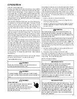
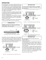
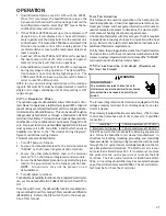
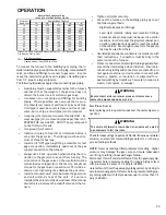
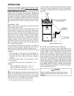
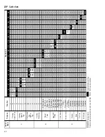
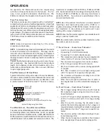
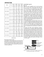
There are 18 DIP switches on the modulating furnace IFC.
Switches are located in 3 rows, each having 6 switches.
Switches are numbered from 1 to 18. The “ON” position is
“UP’. The chart shows all 18 DIP switches, their function
and their factory position.
Switches 1 & 2
Select cooling speed A, B, C or D. Factory
setting is D (both switches up in the “ON” position. These
switches are ignored when using a CTK0* communicating
thermostat.
Switches 3 & 4
Select heating speed A, B, C or D. Factory
setting is B (3 ON, 4 OFF) These switches are ignored
when using a CTK0* communicating thermostat.
Switches 5 & 6
Select continuous fan speed A, B, C or D.
Factory setting is B (5 ON, 6 OFF) These selections are based
off of percentages of the maximum CFM that each model
furnace is rated for; A = 25%, B = 50%, C = 75%, D = 100%.
These switches are ignored when using a CTK0* communi-
cating thermostat.
Switches 7 & 8
Select cooling ramping profiles A, B, C or
D. Factory setting is A (both switches down in the “OFF”
position).Each ramping profile provides a different routine
for the indoor blower motor to follow in a call for cooling.
Rather than bringing the motor up to cooling speed imme-
diately, ramping profiles bring the motor up to cooling speed
in stages.
NOTE
:
Reductions in CFM for ramping are not added to re-
ductions in CFM for DEHUM. Example; CFM is reduced for
the fist several minutes of a cooling call by 15%, if a call for
DEHUM is present during this CFM reduction; CFM will not
be reduced by another 15%. Rather, after the ramping time
period has expired, the CFM would continue at the 15% re-
duction to satisfy the DEHUM request. These switches are
ignored when using a CTK0* communicating thermostat .
Switches 9 & 10
Select CFM Trim Adjustment. Choices
are 0%, + 10%, -10%. Factory setting is A. Trim adjustments
add or subtract from the CFM selections made by heat and
cool CFM selections. Trim adjustments affect cooling, and
heating fan speeds. These switches are ignored when using
a CTK0* communicating thermostat .
Switches 11 & 12
Select fan off delay in heat. Choices are
90, 120, 150, or 180 seconds. Factory setting is C, 150
seconds. These switches are ignored when using a CTK0*
communicating thermostat.
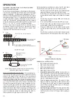
Switch 13
Selects thermostat type for heating. Factory
setting for this switch is OFF, this is the correct setting for
a conventional single stage stat or a CTK02**, CTK03 and
CTK04 communicating-modulating stats. To use a conven-
tional two stage heating thermostat or a CTK01 thermo-
stat, move this switch to the ON position.
Switch 14
Selects compressor setup for cooling. Factory
position is OFF. This is the correct position for a single
stage condensing unit. In this position, Y from the room
thermostat would connect to Y1 on the IFC. Full CFM se-
lected by switches 1 & 2 will be delivered during a Y1 call. If
using a two stage outdoor unit, move this switch to the ON
position and wire Y1 from the room stat to Y1 on the IFC,
wire Y2 on the room stat to Y2 on the IFC. This switch is
ignored when using a CTK0* communicating thermostat.
Switch 15
Selects DEHUM. Enabling this feature will re-
duce CFM in a call for cooling by 15%. Factory position is
OFF, in this position DEHUM is disabled. To use this fea-
ture the DIP switch must be turned to the ON position and a
normally closed dehumidistat be used. This switch is ig-
nored when using a CTK0* communicating thermostat.
Switches 16, 17, 1
8 These are system switches critical to
the ClimateTalk™ communicating network and must be left
in the factory enabled ON position.
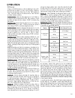
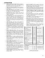
System
System Operating
Mode
Airflow Demand Source
Cooling
Air Conditioner
Heating
Furnace
Continuous Fan
Thermostat
Cooling
Heat Pump
Heat Pump Heating
Only
Heat Pump
Auxiliary Heating
Furnace
Continuous Fan
Thermostat
Cooling
Furnace
Heating
Furnace
Continuous Fan
Thermostat
F Non-
Comm 1stg Air
Conditioner
Air Conditioner +
Furnace
Heat Pump +
Furnace
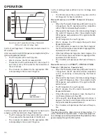
For example, assume the system is an air conditioner
matched with a furnace. With a call for low stage cooling,
the air conditioner will calculate the system’s low stage cool-
ing airflow demand. The air conditioner will then send a
fan request along with the low stage cooling airflow de-
mand to the furnace. Once received, the furnace will send
the low stage cooling airflow demand to the ECM motor.
The ECM motor then delivers the low stage cooling airflow.
See the applicable ComfortNet air conditioner or heat pump
installation manual for the airflow delivered during cooling
or heat pump heating.
In continuous fan mode, the CTK0* thermostat provides the
airflow demand. The CTK02**, CTK03 and CTK04 thermo-
stats may be configured for one of threecontinuous fan speed
settings allow for 25%, 50% or 75% airflow, based on the
furnaces’ maximum airflow capability. During continuous
OPERATION

