background image

CKT04 ADDENDUM

105

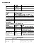
Set-Up

s

t

n

e

m

m

o

C

s

n

o

it

p

O


e

l

b

a

if

i

d

o

M

 r

e

s

U

m

e

tI


u

n

e

m

b

u

S

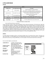
Choose the opera

on mode of Humidi

er 

(This selec

on is only displayed if HUM is selected in ACC)

HUM FAN SPD (%)

25%, 50%*, 75% , 100%

Choose the indoor fan speed at the 

me of humidi

ca

on

 (This selec

on is only displayed if IND is selected 

in HUM and HUM is selected in ACC)

ACC

HUM, W/BLWR, NONE*

Choose Accessory 

(Humidi

er, any other accessory requiring blower or none)

HT KIT (kW)

All valid HT op

ons

Chose valid heater kit installed (Default se

ng is set to 'no heater kit')

Heat Air

ow Trim

(%) (HT TRM)

0*, 2, 4, 6, 8, 10

Trims the hea

ng air

ow by the selected amount

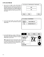
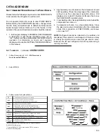
SET-UP

HUM

OFF*, ON, IND

ADVANCED FEATURES SET-UP MENU CHART

Note: Default factory se

ttings

 are marked with *.

The set-up menu allows for selecting accessories that may have been connected to the indoor unit. User can 

choose between humidifier, w / 

BLWR

 for an accessory which is run in conjunction with the blower or none if 

no accessory is connected. 

HUM

 (humidity setting) selection is only displayed if hum is selected in 

ACC

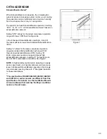
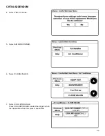
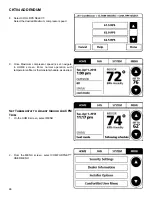
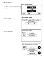
. User 

can choose the operation mode of humidifier. 

HUM FAN SPD

 (humidity airflow) selection is only displayed if 

IND

 is selected in 

HUM

 and 

HUM

 is selected in 

ACC

. User can choose the indoor fan speed trim at the time 

of humidification. Heater kit selection can also be done from this menu. It is very important to select the 

correct heater kit value for normal operation of the system. The set-up menu allows for selecting the trim 

adjustment of nominal electric heat airflow from 0% to 10% (in 2% incremental steps). 

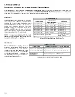
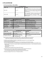
Status

This menu displays information about the systems current status. This menu can be utilized to confirm cor

-

rect functionality of the equipment and for troubleshooting purposes. It can also be used to compare mea

-

sured airflow values to the value reported by the air handler. The following items will be displayed:

The following items will be displayed:

Current Mode:


Current System Operation 


Mode (COOL, HEAT, FAN, AUX 

   HEAT, 

DEFROST, 

ON).

Current Airflow:  

Indoor Unit Airflow (CFM)

Liq Gas Temp:   

ID Coil Inlet Temp, ID Coil Out- 


let Temp (HEATING MODE)

Pressure:


Indoor Coil Pressure Sensor  


Reading

Refrigerant:   

R-410A

SH and SC:    

ID Superheat (COOLING  


MODE), ID Subcooling 


   (HEATING 

MODE)

Fan Run Time:   

Provides ID Fan Run Time in  


Hours

Summary of Contents for DX20VC Series

Page 1: ...per service or service procedures If you service this unit you assume responsibility for any injury or property dam age which may result In addition in jurisdictions that require one or more licenses to service the equipment specified in this manual only licensed personnel should service the equipment Improper installation adjustment servicing or repair of the equip ment specified in this manual o...

Page 2: ...NT DOES CONTACT YOUR SKIN OR EYES SEEK MEDICAL HELP IMMEDIATELY ALWAYS FOLLOW EPA REGULATIONS NEVER BURN RE FRIGERANT AS POISONOUS GAS WILL BE PRODUCED WARNING THE UNITED STATES ENVIRONMENTAL PROTECTION AGENCY EPA HAS ISSUED VARIOUS REGULATIONS REGARDING THE INTRODUCTION AND DISPOSAL OF REFRIGERANTS INTRO DUCED INTO THIS UNIT FAILURE TO FOLLOW THESE REGULATIONS MAY HARM THE EN VIRONMENT AND CAN LE...

Page 3: ...protective cover is properly in place If however the terminal protective cover is not properly in place a venting terminal may discharge a combination of a hot lubricating oil and refrigerant b flammable mixture if system is contaminated with air in a stream of spray which may be dangerous to anyone in the vicinity Death or serious bodily injury could occur Under no circumstances is a hermetic com...

Page 4: ...tons Compressor S Single Stage V Variable Speed T Two Stage Feature Set A Base D Deluxe N Nominal D V 24 P E C C 1 A AA 1 2 3 4 5 6 7 8 9 10 11 12 Brand Engineering D Daikin Single Piece Major Minor revisions Air Handler Not used for inventory management Refrigerant Compatability 4 R 410A Variable Speed Motor Electric Normal Capacity Range 1 208 230 V 1 Phase 60 Hz 25 2 Tons 59 4 Tons 37 3 Tons 61...

Page 5: ...spring Number of turns from SS to loosespring R22 7 25 4 25 R410A 9 5 2 R410A 0 6 C turn 1 1 F turn R410A Max 75 C 167 F Number of turns Number of turns from SS to from SS to TIGHT Spring LOOSE Spring R410A 9 5 2 Model Name TXV Kit DX20VC0241 TXV V24 DX20VC0361 TXV V36 DX20VC0481 TXV V48 DX20VC0601 TXV V60 ...

Page 6: ...t Selec on DV25PECB14A DV37PECC14A DV59PECD14A DV61PECD14A S 9 S 10 S 11 S 12 No heater OFF OFF OFF OFF First 3 5 5 5 ON ON ON ON Second 5 6 6 6 ON ON ON OFF Third 6 8 8 8 ON ON OFF ON Fourth 8 10 10 10 ON ON OFF OFF Fi h 10 15 15 15 ON OFF ON ON Sixth X 19 20 20 ON OFF ON OFF Seventh X X X 25 ON OFF OFF ON VALID SWITCH SETTINGS 3 k n a B S D d r a o B l o r t n o C r o o d n I g n i t t e S h c t...

Page 7: ...SPECIFIED MEASUREMENT POSITION USING A VOM WHILE PAYING ATTENTION NOT TO TOUCH THE CHARGED AREA 4 IMMEDIATELY AFTER MEASURING THE RESIDUAL VOLTAGE DISCONNECT THE CONNECTORS OF THE OUTDOOR UNIT S FAN MOTOR IF THE FAN BLADE ROTATES BY STRONG WIND BLOWING AGAINST IT THE CAPACITOR WILL BE CHARGED CAUSING THE DANGER OF ELECTRICAL SHOCK WARNING Žæ t à ï ª L é ƒR ƒ ƒf ƒ ƒT Ìi à j Ì i à j ƒR ƒ ƒf ƒ ƒT Žæ ...

Page 8: ...HE STATIC ELECTRICITY FROM YOUR BODY TO PREVENT FAILURE OF THE PC BOARD 3 MEASURE THE RESIDUAL VOLTAGE IN THE SPECIFIED MEASUREMENT POSITION USING A VOM WHILE PAYING ATTENTION NOT TO TOUCH THE CHARGED AREA 4 IMMEDIATELY AFTER MEASURING THE RESIDUAL VOLTAGE DISCONNECT THE CONNECTORS OF THE OUTDOOR UNIT S FAN MOTOR IF THE FAN BLADE ROTATES BY STRONG WIND BLOWING AGAINST IT THE CAPACITOR WILL BE CHAR...

Page 9: ...HE STATIC ELECTRICITY FROM YOUR BODY TO PREVENT FAILURE OF THE PC BOARD 3 MEASURE THE RESIDUAL VOLTAGE IN THE SPECIFIED MEASUREMENT POSITION USING A VOM WHILE PAYING ATTENTION NOT TO TOUCH THE CHARGED AREA 4 IMMEDIATELY AFTER MEASURING THE RESIDUAL VOLTAGE DISCONNECT THE CONNECTORS OF THE OUTDOOR UNIT S FAN MOTOR IF THE FAN BLADE ROTATES BY STRONG WIND BLOWING AGAINST IT THE CAPACITOR WILL BE CHAR...

Page 10: ...rol board behind the refrigerant tubing as shown Fixing screw A Cover Refrigerant Tubing Heat sink for cooling fixing screws B Install the control board When working on a service port ensure that no refrigerant and or compressor oil is sprayed onto the control board This could damage the board s functionality 1 Wipe the stale grease completely from the installed pip ing If you reinstall the contro...

Page 11: ...n The indoor evaporator coil functions to cool and dehumidify the air conditioned spaces through the evaporative process taking place within the coil tubes NOTE The pressures and temperatures shown in the re frigerant cycle illustrations on the following pages are for demonstration purposes only Actual temperatures and pressures are to be obtained from the Expanded Perfor mance Chart Liquid refrig...

Page 12: ...el and allows the user to set a dehumidification target based on these settings The thermostat controls the humidity level of the conditioned space using the cooling system Dehumidifica tion is engaged whenever a cooling demand is present and structural humidity levels are above the target level When this condition exists the circulating fan output is reduced increasing system run time over coolin...

Page 13: ...or unit completely if the system is overcharged or if there is a de lay in closing the liquid service valve and gas service valve Evacuate the left over refrigerant from the system using a recovery machine System Test The mandatory system verification test is enabled from this SYSTEM TEST menu which enables a functional check of the equipment in addition to ensuring proper stop valve position Cool...

Page 14: ...ax Compressor RPS Max RPS Offset Max compressor speed at which the outdoor unit will operate can be changed using thermostat Max compressor speed can be changed to get the required capacity or efficiency Once the maximum speed is set the system operates be tween the set maximum speed and default low speed Based on the compressor speed displayed in MAX COMPRESSOR RPS the maximum compressor speed ca...

Page 15: ... Liquid Ball Valve Gas Fan Motor Hex HP LP HP LP sensor Ta Thermistor HPS Outdoor unit Indoor unit TXV Accumulator Tm Thermistor T Thermistor Oil separator Filter Compressor Crankcase heater Capillary tube Reversing Valve Hex Fan Motor Filter dryer Stop Valve Liquid Ball Valve Gas Fan Motor Hex HP LP HP LP sensor Tm Thermistor Ref cooling Ta Thermistor Outdoor unit Indoor unit TXV Check valve Td T...

Page 16: ...ischarge Temperature Ta Thermistor Outdoor Air Temperature Tm Thermistor Outdoor Coil Temperature Tli Thermistor Indoor Liquid Temperature Tgi Thermistor Indoor Gas Temperature ID HP LP sensor Indoor High Low Pressure Sensor OD HP LP sensor Outdoor High Low Pressure Sensor HPS High Pressure Switch ...

Page 17: ...en X X X X X X X X X X Gas stop valve does not fully open X X X X X X Line set restriction X X X X X X X X X X Line set length is too long X X X X X Blocked filter dryer X X X X X X X X X X ID EEV coil failure X X X X X X X X X X X X X X X X X ID EEV failure X X X X X X X X X X X X X X X X Check valve failure Blocked X X X X X X X X X High Pressure switch failure X Pressure sensor failure X X X X ...

Page 18: ...HEATER ELEMENTS 26 S 60 ELECTRIC HEATER OPTIONAL ITEM 26 S 61A CHECKING HEATER LIMIT CONTROL S 27 S 61B CHECKING HEATER FUSE LINK 27 OPTIONAL ELECTRIC HEATERS 27 S 100 REFRIGERATION REPAIR PRACTICE 27 S 101 LEAK TESTING NITROGEN OR NITROGEN TRACED 28 S 102 EVACUATION 28 S 103 CHARGING 29 S 104 CHECKING COMPRESSOR EFFICIENCY 29 S 105B THERMOSTATIC EXPANSION VALVE 30 S 106 OVERFEEDING 30 S 107 UNDER...

Page 19: ...NG LINE VOLTAGE NOW PRESENT With power ON thermostat calling for cooling 1 Use a voltmeter to check for 24 volt at thermostat wires C and R in the indoor unit control panel 2 No voltage indicates trouble in the thermostat wiring or transformer source 3 Check the continuity of the thermostat and wiring Re pair or replace as necessary WARNING LINE VOLTAGE NOW PRESENT Resistance Heaters With power ON...

Page 20: ...y be improved by using a high quality shielded twisted pair cable for the data transmission lines Finally be sure to confirm that the wires do not come off each terminal after all connections are finished TWO WIRE OUTDOOR FOUR WIRE INDOOR WIRING Typical wiring will consist of two wires between the indoor unit and outdoor unit and four wires between the indoor unit and thermostat The figure that fo...

Page 21: ... 13 CHECKING INDOOR OUTDOOR HI LOW PRES SURE SENSOR With power ON WARNING LINE VOLTAGE NOW PRESENT The HI LOW and indoor pressure sensor senses the suc tion pressure in cooling mode and the discharge pressure in heating mode Follow the following sequence to check the pressure sensor 1 Connect a voltmeter across the sensor terminals be tween black and white wirings The voltmeter should show the vol...

Page 22: ...ent heat source Ignition of the discharge can also occur at the venting ter minal or inside the compressor if there is sufficient contam inant air present in the system and an electrical arc occurs as the terminal vents Ignition cannot occur at the venting terminal without the presence of contaminant air and cannot occur externally from the venting terminal without the presence of an exter nal ign...

Page 23: ...8 TESTING CRANKCASE HEATER 5 TON ONLY The crankcase heater must be energized a minimum of 2 hours before the unit is operated Crankcase heaters are used to prevent migration or accumulation of refrigerant in the compressor crankcase during the off cycles and pre vents liquid slugging or oil pumping on start up A crankcase heater will not prevent compressor damage due to a flood back or overcharge ...

Page 24: ... motor connector on the control board Voltage should be be tween 9 and 15 VDC Replace control if voltage is not as specified Electric Heat Sequencer Outputs WARNING HIGH VOLTAGE DISCONNECT ALL POWER BEFORE SERVICING OR INSTALLING THIS UNIT MULTIPLE POWER SOURC ES MAY BE PRESENT FAILURE TO DO SO MAY CAUSE PROPERTY DAMAGE PERSONAL INJURY OR DEATH 1 Turn on power to air handler or modular blower WARN...

Page 25: ...VOLTAGE NOW PRESENT 2 Check voltage between pins 1 and 4 at the 4 wire motor connector on the control board Voltage should be be tween 9 and 15 VDC Replace control if voltage is not as specified Electric Heat Sequencer Outputs WARNING HIGH VOLTAGE DISCONNECT ALL POWER BEFORE SERVICING OR INSTALLING THIS UNIT MULTIPLE POWER SOURC ES MAY BE PRESENT FAILURE TO DO SO MAY CAUSE PROPERTY DAMAGE PERSONAL...

Page 26: ...nents such as a Heating Cooling Thermostat and Outdoor Thermostats are available to complete the in stallation HEATER KIT CAPACITY SETTING DV PEC For heater kit installation it is important to set the capacity of the electric heater at the communicating thermostat and DIP switch Setting with communicating thermostat For a detailed procedure of thermostat heater kit capacity selection process pleas...

Page 27: ...dual heater element is protected with a one time fuse link which is connected in series with the element The fuse link will open at approximately 333 F WARNING DISCONNECT ALL POWER BEFORE SERVICING 1 Remove heater element assembly so as to expose fuse link 2 Using an ohmmeter test across the fuse link for conti nuity no reading indicates the link is open Replace as necessary NOTE The link is desig...

Page 28: ... for repair Outdoor section depending on line set length and amount of charge in system may not be able to hold the entire system charge This is the most important part of the entire service proce dure The life and efficiency of the equipment is dependent upon the thoroughness exercised by the serviceman when evacuating air non condensables and moisture from the system Air in a system causes high ...

Page 29: ...rum in liquid form due to its fractionation properties but should be Flashed to its gas state before entering the sys tem There are commercially available restriction devices that fit into the system charging hose set to accomplish this DO NOT charge liquid R410A into the compressor 4 With the system still running close the valve on the charging cylinder At this time you may still have some liquid...

Page 30: ...ck for an overcharged unit by referring to the cooling performance charts in the servicing section 2 Check the operation of the power element in the valve as explained in S 110 Checking Thermostatic Expan sion Valve Operation 3 Check for restricted or plugged equalizer tube S 107 UNDERFEEDING Underfeeding by the thermostatic expansion valve results in low system capacity and low suction pressures ...

Page 31: ...subtract 109 F from 120 F The difference is 11 subcooling See the specification sheet or technical information manual for the design subcooling range for your unit There are other causes for high head pressure which may be found in the Cooling Heating Analysis Chart If other causes check out normal an overcharge or a system containing non condensables would be indicated If this system is observed ...

Page 32: ...OTE Not more than 0 8 lb 13 oz of refrigerant be added to the system at a time to achieve the target sub cooling It is recommended adding 4 oz refrigerant each time then wait 20 minutes to stabilize the system 4 Disconnect manifold set Installation is complete S 110 CHECKING EXPANSION VALVE OPERATION 1 Remove the remote bulb of the expansion valve from the suction line 2 Start the system and cool ...

Page 33: ...horizontal suction line Liquid Line Suction Line Wrapped in Armaflex Metal Sleeve Hanger Wall Stud Liquid Line Strapped to Suction Line Figure 1 1 Installa on of Refrigera on Piping From Ver cal to Horizontal Outside Wall Inside Wall Liquid Line Suction Line IMPORTANT Refrigerant lines must not touch wall Strap Sleeve Strap Sleeve Wire Tie Wire Tie PVC Pipe Caulk Outside Wall Armaflex Wrapped Suct...

Page 34: ...N 3 OUTDOOR UNIT IS ABOVE THE INDOOR UNIT Condenser ABOVE Evaporator Maximum vertical separation of 200 ft Maximum line set equivalent length of 250 ft The maximum line set actual length is 200 ft Includes pressure losses of any elbows bends etc 1 Suc on line must be sloped con nuously towards the indoor unit 2 The maximum eleva on ver cal difference between the outdoor unit and indoor unit is 200 ...

Page 35: ...harge level as shown in the unit serial plate For longer line sets greater than 15 feet add 0 6 ounces of refrigerant per foot NOTICE TOTAL REFRIGERANT FACTORY CHARGE 0 6 OZ FT ADDITIONAL FEET OF ACTUAL LINE SET BURYINGREFRIGERANTLINES If burying refrigerant lines can not be avoided use the following checklist 1 Insulate liquid and suc on lines separately 2 Enclose all underground por ons of the r...

Page 36: ...ing a draft gauge inclined manometer measure the static pressure of the return duct at the inlet of the unit Negative Pressure 2 Measure the static pressure of the supply duct Positive Pressure 3 Add the two 2 readings together for total absolute val ue of external static pressure for example 0 30 wc 0 20 wc 0 50 wc total static pressure TOTALEXTERNALSTATIC NOTE Both readings may be taken simultan...

Page 37: ... System Opera ng Mode Airflow Demand Source Cooling Outdoor Unit Heat Pump Hea ng Only Outdoor Unit Con nuous Fan Thermostat HP Electric Heat Strips Either Outdoof Unit or Indoor Unit which has higher Airflow demand Electric Heat Strips Only Indoor Unit Gas Furnace Combus on Heat Indoor Unit Any Air Handler or Modular Blower For example assume the system is an outdoor unit matched with an indoor uni...

Page 38: ... handler is equipped with a variable speed circulator blower This blower provides several automatically adjusted blower speeds The Specification Sheet applicable to your model provides an airflow table showing the relationship between airflow CFM and external static pressure E S P The electric heat dip switch default position is set to the OFF OFF OFF position and should be adjusted by the install...

Page 39: ...t touch ungrounded objects etc If you come in contact with an ungrounded object repeat step 2 before touching control or wires 4 Discharge your body to ground before removing a new control from its container Follow steps 1 through 3 if installing the control on a blower Return any old or new controls to their containers before touching any un grounded object INDOOR UNIT TROUBLESHOOTING FOR TXV APP...

Page 40: ...SERVICING 40 INDOOR UNIT TROUBLESHOOTING FOR TXV APPLICABLE UNIT MBVC 00AA 1 DIAGNOSTIC CODES ...

Page 41: ...A LL EC Heater kit selected via dipswit ches is too small for heater kits in shared data set Verify electric heat dipswit ch set tings Verify the installed electric heater is valid for the air handler blower Check nameplate or Specification Sheet applicable to your model for allowable heat er kit s Verify shared data set is correct for the specific model Re pop ulat e data using correct memory car...

Page 42: ...Air handler blower does not contain any shared data Populate shared data set using memory card Turn power OFF prior to repair Use memory card for the specific model Insert memory card BEFORE turning power ON Memory card may be removed after data is loaded Error code will be cleared once data is loaded Turn power off before removing memory card Air handler blower fails to operate Integrated control...

Page 43: ...ATCH b2 Incorrect circulator blower motor in air handler blower Incorrect shared data set in integrated control module Verify circulator blower motor horse power is the same specified for the specific air handler blower model Replace is necessary Verify shared data set is correct for the specific model Re populate data using correct memory card if required Turn power OFF prior to repair Replace mo...

Page 44: ...ine voltage to blower is within the range specified on the air handler blower rating plate See Installation Instructions for installation requirements Turn power OFF prior to repair Air handler blower fails to operate Integrated control module LED display provides indicated error code ComfortNet thermostat Call for Service icon illuminated ComfortNet thermostat scrolls Check Air Handler message b7...

Page 45: ...or fire alarms TB5 SWITCH ALARM TB4 The auxiliary alarm switch must be normally closed and open when the alarm occurs For example a normally closed con densate switch will open when the base pan s water level reaches a particular level The control will respond by turning off the blower motor and displaying the proper fault codes If the switch is later detected closed for 30 seconds normal operatio...

Page 46: ...NG THIS UNIT MULTIPLE POWER SOURC ES MAY BE PRESENT FAILURE TO DO SO MAY CAUSE PROPERTY DAMAGE PERSONAL INJURY OR DEATH Refer to the Troubleshooting Chart at the end of this manual for assistance in determining the source of unit operation al problems The 7 segment LED display will provide any active fault codes An arrow printed next to the display indi cates proper orientation arrow points to top...

Page 47: ... TO MOTOR b9 LOW INDOOR AIRFLOW Minor Error Code without EH mode 9b LOW INDOOR AIRFLOW Major Error Code EH mode only 70 EEV DISCONNECTION DETECTED 73 LIQUID SIDE THERMISTOR ABNORMALITY 74 GAS SIDE THERMISTOR ABNORMALITY 75 PRESSURE SENSOR ABNORMALITY 77 INDOOR UNIT THERMOSTAT COMMUNICATION ERROR STARTUP OPERATION DURING OPERATION Hu HUMIDIFICATION DEMAND Running without heating FC FAN COOL COMMUNI...

Page 48: ...emajorerrorcodein normalmode 2 digit7 segment displays keep showing error code indoorunit In theevent indooruniterrorcodeto solvethe For example if the CFM is 1240CFM 7 segmentdisplayshows 7 Segment LED Display State Descrip on of Condi on No Display INTERNAL CONTROL FAULT NO POWER On STANDBY WAITING FOR INPUTS FC FAN COOL COMMUNICATING MODE ONLY Fan Demand Cool FH FAN HEAT COMMUNICATING MODE ONLY...

Page 49: ... s havingsomeminorerrorcodeduringdefrostopera onin normalmode 2 digit7 segmentdisplaysshowstate dF errorcodeand air owstatus 2 Error code 3 Air ow 3 Whenthe uni s havingsomeminorerrorcodein normalmode 2 digit7 segmentdisplaysshowerror codeand air owstatus 5 Whenthe uni s havingsomeminorerrorcodein emergencymode 2 digit7 segmentdisplaysshow state EE and errorcode ...

Page 50: ... how to use the mode display DISPLAY The display consists of 2 digits DISPLAY BUTTON LAYOUT The display bu ons shown can be used to navigate and select items FAULT CODE HISTORY NAVIGATION This mode will allow the user to see the six most recent system faults Please follow the flow chart to navigate to error codes from screen zero For a list of the fault codes please see the TROUBLESHOOTING tables i...

Page 51: ...REENZER O Hold Fault Recall for more than 2 sec Release Fault Recall between 2 to 5 sec Hold Fault Recall for more than 5 sec Flashing Display First Error Code Last Error Code Press Fault Recall for Error Code Press Fault Recall for Error Code Press Fault Recall to complete list Release Fault Recall in less than 2 sec Flashing Display Solid Display 88 for 3 sec before erasing all Diagnos c Codes S...

Page 52: ...4 and TB5 if not used d0 E_d0 Data Not Yet On Network NO NET DATA d r a c y r o m e m g n i s u t e s a t a d d e r a h s e t a l u p o P k r o w t e n e h t n o a t a d d e r a h s o N k r o w t e N n o t o n a t a D d1 E_d1 Invalid Data On Network INVALID DATA d r a c y r o m e m g n i s u t e s a t a d d e r a h s e t a l u p o P k r o w t e n e h t n o a t a d d e r a h s g n o r W k r o w t e...

Page 53: ...r failure Combination mistake of outdoor unit and indoor unit Chec k for obstruc tion on the fan motor Chec k duc twork filter for blockage clean filters Remove obstruction Verify all registers are fully open Chec k the c onnections and the rotation of the motor Verify the input voltage at the motor Verify duc twork is appropriately sized for system Resize replac e duc twork if needed Replac e mot...

Page 54: ...perating status will not be shown in the thermostat status menu or on the out door 7 segment displays The 7 segment displays on indoor control board will display EE 1 HEATING EMERGENCY MODE Emergency Heating mode is to be used when communica tion between the indoor unit and thermostat are not function ing properly This mode will run the electric heat strips inde pendently of any thermostat in one ...

Page 55: ...Fi h 10 15 15 15 ON OFF ON ON Sixth X 19 20 20 ON OFF ON OFF Seventh X X X 25 ON OFF OFF ON Heater Kit Selec on Heater kW Switch Bank DS 3 Indoor Control Board Se ngs Dip Switch Se ng S 21 S 22 OFF OFF ON OFF OFF ON ON ON S 1 S 2 ON ON ON OFF OFF ON OFF OFF Switch Bank DS 2 Outdoor Control Board Se ngs Func on Normal opera on Emergency Mode Cooling Emergency mode Low cool Level Cooling Emergency m...

Page 56: ...ted even if the compressor has stopped The in door unit will continue to operate the electronic expansion valve for refrigerant super heat control and the compressor will cycle at the interval selected by dip switch bank DS 2 DS2 1 DS2 2 ON ON Normal Opera on ON OFF Emergency Mode Low Cool Level OFF ON Emergency Mode Medium Cool Level OFF OFF Emergency Mode High Cool Level Dip Switch Posi on Func ...

Page 57: ...ency Mode 13 ON Allow in Emergency Mode Fan Emergency Mode 14 OFF Allow in Emergency Mode Fan Emergency Mode 15 ON EEV Enable 16 OFF No Use 17 ON Emergency EEV Opening 18 OFF Emergency EEV Opening 19 OFF EEV Emergency Mode 20 OFF No Use 21 OFF Emergency mode Cooling Hea ng Emergency Mode 22 OFF Emergency mode Cooling Hea ng Emergency Mode 23 OFF No Use 24 OFF No Use 1 ON CT Communica on Enable 2 O...

Page 58: ...wired when selecting a cooling airflow Note the blower will run continuously with this wiring which is required The out door unit will cycle as described in the Cooling Emergency Mode section when appropriate dip switch modes are set 1 2 R C G W1 W2 Y1 Y2 0 DEHUM Indoor Unit Integrated Control Module Note Emergency heating mode is not available with TXV applicable indoor units If communications st...

Page 59: ... on Each mode has its own corresponding Screen within the display itself which allows the user to navigate and use the features Example The Fault Code is accessed and displayed from Screen 0 of the 7 segment display The Fault History is accessed and display using Screen 1 of the display etc FAULT CODE FAULT HISTORY MONITORING SETTING MODE 1 SETTING MODE 2 MODE Fault Code Display Fault Code History...

Page 60: ...play This shows the most recent fault To access hold the RECALL bu on for 5 seconds at screen 0 To access hold the RECALL bu on for 5 seconds at screen 1 To access hold the RECALL bu on To access hold the RECALL and TEST bu ons simultaneously To return to SCREEN 0 of the display press the LEARN bu on for 5 seconds at screen 2 for 5 seconds at screen 2 The first digit displays the SCREEN Hold RECALL...

Page 61: ...GATION SCREEN This mode will allow the user to see the six most recent system faults For a list of the fault codes please see the TROUBLESHOOTING tables in this document 1 SCREEN 0 SCREEN 1 The display will change to SCREEN 1 Displays 2nd most recent Fault code 6th most recent Fault Code Hold RECALL Press RECALL Press RECALL Press RECALL Press RECALL ...

Page 62: ...firm the setting Press RECALL Press RECALL Item number Display flickers at 1 second intervals Value MONITORING MODE NAVIGATION SCR This screen allows the user to monitor system variables as shown in the tables at the end of this sec on EEN 2 OFF ON Blink interval 0 4 sec On 0 4 sec Off Hold RECALL Press RECALL Press RECALL Press RECALL ...

Page 63: ...just system se ngs as shown in the tables at the end of this sec on SCREEN 0 Press RECALL Press RECALL to increase the value Press TEST to change setting Press RECALL Press TEST to complete setting and return to setting mode SCREEN 2 Press LEARN SCREEN 3 Press RECALL Press RECALL OFF ON Blink interval 0 4 sec On 0 4 sec Off ...

Page 64: ...to increase the number Press RECALL Press TEST to change setting Press RECALL Press TEST to complete setting and return to setting mode Press RECALL Press RECALL Press RECALL SCREEN 0 OFF ON Blink interval 0 4 sec On 0 4 sec Off Press RECALL Press RECALL SCREEN 4 Se ng Mode 2 allows the user to change system se ngs See table in back of this sec on ...

Page 65: ...ODE Setting No s e t o N s t n e t n o C 1 Compressor operation time unit hr Multiply by 200 2 Operation code 0 Stop 1 Cooling Start up 3 Oil Return Operation 6 Cooling Operation 3 Compressor Reduction Mode 0 OFF 1 ON 4 demand unit Cut off the decimal first place 5 act demand unit Cut off the decimal first place 6 Requested ID CFM unit CFM Multiply by 10 7 Reported ID CFM unit CFM Multiply by 10 8...

Page 66: ... m i r t l a n o i t i d d a r o f d e s U 5 2 1 basic airflow trim setting This setting affects all trim settings except 15 High cooling or heating SCREEN 3 SETTING MODE 1 Setting NOTE Parameters as per factory se ng are highlighted in bold and underlined The specifica on of DX20VC0241BD 0361BC 0481BC and 0601BC or earlier models are different from this specifica on For details see the Installa on M...

Page 67: ...needed Replace control board if necessary Replace indoor unit with TXV applicable indoor unit 16 LOW PRESSURE M This error indicates the equipment is experiencing frequent low pressure faults Control has determined continued operation is acceptable This indicates they may be a problem with the equipment Stop valve not completely open Restriction in refrigerant lines Low refrigerant charge Refriger...

Page 68: ...properly fastened 2 4 ton only No or poor thermal grease coating between cooling plumbing and cooling bracket on control board 2 4 ton only Outdoor fan low speed 5 ton only No flow or limited flow through control board cooling circuit potential restriction in line or low refrigerant 2 4 ton only Stop valve not completely open 2 4 ton only Cycle power re try during usable ambient temperature range ...

Page 69: ...s a high power supply voltage condition High line voltage supply Verify unit is connected to power supply as specified on rating plate Correct high line voltage condition Contact local utility if needed 44 E44 OP TEMP RANGE The control detects the outdoor temperature outside recommended operational range Unit may continue to operate normally Ambient air conditions too high or low Cycle power re tr...

Page 70: ...indoor blower motor Indoor fan motor not properly connected Too much static pressure Check ID fan motor wiring and connectors Repair replace if needed Check ID fan motor Replace if needed B9 Eb9 LOW ID AIRFLOW Estimated airflow from motor is lower than the airflow requirement Failed indoor blower motor Indoor fan motor not properly connected Too much static pressure Check ID fan motor wiring and c...

Page 71: ...to the outdoor unit 7 Remove the memory card from the unit 8 Connect the Climate Talk CT connector to the outdoor unit 9 Turn the power ON to the outdoor unit 10 Continue the operation of the unit as desired NOTE 1 If there is an error E11 on the 7 segment display of the Outdoor unit after step 11 run the SYSTEM VERIFICA TION TEST on the Outdoor unit using the thermostat menu AC Menu Air Condition...

Page 72: ...TROUBLESHOOTING OUTDOOR UNIT 72 Zoomed view of 20 SEER OD Control Board ...

Page 73: ...nd the cor responding potential problem Green receive LED Indicates network traffic The table be low indicates the LED status and the corresponding poten tial problem LEARN button Used to reset the network Press the button for approximately 5 seconds to reset the network LED D E L R O L O C e l b a b o r P n o i t a c i d n I s u t a t S e v i t c e r r o C s e s u a C Actions Off Normal e n o N e...

Page 74: ...95 0 76 64 10 3 11 60 140 4 96 0 65 52 76 2 87 65 149 4 16 0 56 43 63 2 64 70 158 3 50 0 48 36 26 2 41 75 167 2 96 0 41 30 27 2 18 80 176 2 51 0 35 25 38 1 97 85 185 2 14 0 30 21 37 1 77 90 194 1 83 0 26 18 06 1 58 95 203 1 58 0 23 15 33 1 41 100 212 1 36 0 20 13 06 1 25 105 221 1 18 0 17 11 17 1 11 110 230 1 02 0 15 9 59 0 99 115 239 0 89 0 13 8 25 0 87 120 248 0 78 0 12 7 13 0 77 125 257 0 68 0 ...

Page 75: ... 9 364 110 0 466 0 128 7 596 148 4 60 8 6 162 57 0 264 87 4 366 110 4 468 0 129 0 600 149 0 62 10 0 164 57 7 266 87 9 368 110 8 470 0 129 3 604 149 5 64 11 3 166 58 4 268 88 4 370 111 2 472 0 129 7 608 150 1 66 12 6 168 59 0 270 88 9 372 111 6 474 0 130 0 612 150 6 68 13 8 170 59 8 272 89 4 374 112 0 476 0 130 3 616 151 2 70 15 1 172 60 5 274 89 9 376 112 4 478 0 130 7 620 151 7 72 16 3 174 61 1 2...

Page 76: ...326 335 90 92 94 96 88 90 92 94 86 88 90 92 84 86 88 90 82 84 86 88 80 82 84 86 345 354 364 374 98 100 102 104 96 98 100 102 94 96 98 100 92 94 96 98 90 92 94 96 88 90 92 94 384 395 406 416 106 108 110 112 104 106 108 110 102 104 106 108 100 102 104 106 98 100 102 104 96 98 100 102 427 439 450 462 114 116 118 120 112 114 116 118 110 112 114 116 108 110 112 114 106 108 110 112 104 106 108 110 474 4...

Page 77: ...o change Always refer to the wiring diagram on the unit for the most up to date wiring NOTE The compressor can operate normally in any of the following wiring connec ons shown on the right Wiring connec on between control board and compressor terminal U V W U V W U V W U V W Wiring connec on 2 Wiring connec on 3 Control Board Terminal side Compressor Terminal side U V W U V W Wiring connec on 1 DX...

Page 78: ...ect to change Always refer to the wiring diagram on the unit for the most up to date wiring NOTE The compressor can operate normally in any of the following wiring connec ons shown on the right Wiring connec on between control board and compressor terminal U V W U V W U V W U V W Wiring connec on 2 Wiring connec on 3 Control Board Terminal side Compressor Terminal side U V W U V W Wiring connec on...

Page 79: ...ject to change Always refer to the wiring diagram on the unit for the most up to date wiring DX20VC0601 NOTE The compressor can operate normally in any of the following wiring connec ons shown on the right Wiring connec on between control board and compressor terminal U V W U V W U V W U V W Wiring connec on 2 Wiring connec on 3 Control Board Terminal side Compressor Terminal side U V W U V W Wiri...

Page 80: ...agram on the unit for the most up to date wiring HIGH VOLTAGE DISCONNECT ALL POWER BEFORE SERVICING OR INSTALLING THIS UNIT MULTIPLE POWER SOURCES MAY BE PRESENT FAILURE TO DO SO MAY CAUSE PROPERTY DAMAGE PERSONAL INJURY OR DEATH INDOOR UNIT FOR TXV APPLICABLE UNIT MBVC 00AA 1 ...

Page 81: ...R MORE THAN 2 SECONDS WHILE IN STANDBY NO THERMOSTAT INPUTS 6 RED STATUS LED PROVIDES NETWORK STATUS GREEN RX LED INDICATES NETWORK TRAFFIC USE LEARN BUTTON TO RESET NETWORK 7 DISCARD CONNECTOR PL1 WHEN INSTALLING OPTIONAL HEAT KIT 8 THE POSITION OF SELECTOR SWITCHES DS1 DS6 INDICATE FACTORY SETTING 9 REMOVE SHORT RED CIRCUITING WIRE AND PUT AUX ALARM SWITCH WHEN INSTALLING AUX ALARM SWITCH DS6 X1...

Page 82: ...d subsystems indoor outdoor unit and between subsystems is the key to unlocking the benefits and features of the ComfortNet system Two way digital communications is accomplished using only two wires The thermostat and subsystem controls are pow ered with 24 VAC Thus a maximum of 4 wires between the equipment and thermostat is all that is required to operate the system CTK04 WIRING NOTE A removable...

Page 83: ... In such case rerun the SYSTEM TEST when the ambient temperature exceeds 20 F 1 Ensure the thermostat is installed 2 Apply power to outdoor and indoor units 3 Start up After the application information is entered the initial system test must be run FOR INVERTER SYSTEM USING COMFORTNET DO NOT INSTALL A TRANSFORMER A C NOTICE The HOME screen will be displayed showing information similar to one of th...

Page 84: ...word The password is the Date Code located on the thermostat and is available by entering the EQUIPMENT STATUS menu and scrolling to the bottom 6 Select YES to continue 7 From the ComfortNet USER MENU select AIR CONDITIONER NOTE Screen may show air handler or furnace depending on the type of system installed ...

Page 85: ...tem test to run for its duration 5 15 minutes EQUIP TEST SCREEN will show the system test is ON once selected System test will operate the outdoor unit and the indoor unit through a series of startup tests Please proceed to the next step and allow for startup tests to complete Do not interrupt power to outdoor unit indoor unit or thermostat during system test ...

Page 86: ...and for both codes to clear Set Thermostat to CHARGE MODE Please follow the following sequence to enter CHARGE MODE CHARGE mode allows for charging of the system System operates for a duration of approximately one hour while the equipment runs at full capacity After one hour the CHARGE MODE ends and the system resumes normal thermostat operation Before starting the CHARGE MODE turn off the electri...

Page 87: ...Installer password The password is the Date Code located on the thermostat and is available by entering the EQUIPMENT STATUS menu and scrolling to the bottom 4 Select YES to continue 5 Select Air Conditioner 6 Select MAINTENANCE ...

Page 88: ...TEM menu on the main screen If charging is not complete after 1 hour repeat 7 and 8 Refer to S 103 for refrigerant charge level adjustment 9 To terminate CHARGE MODE select CHARGE mode screen again Press OFF Press DONE to terminate CHARGE MODE 10 Once CHARGE MODE is complete and has been terminated navigate to HOME screen Enter normal operation with temperature offset or thermostat schedule as des...

Page 89: ...bling BOOST MODE will provide the quietest and most efficient operation NOTE BOOST MODE applies to DX20VC0 1AC or later model revisions BOOST MODE performance is most effective when paired with an electronic expansion valve enabled indoor unit BOOST MODE is ON by default and is activated when the outdoor temperature reaches 105 F BOOST MODE can be disabled and enabled and the activation temperatur...

Page 90: ...the red Cancel button and selecting the Dealer information button b Once recorded click the green OK button and return to the previous step 4 Select YES to continue 5 Select AIR CONDITIONER 6 Select SYS SETUP Menu ComfortNet User Menu Help Air Handler Previous Menu Help EQUIP TEST SYS SETUP MAINTENANCE COOL SET UP Previous Menu ...

Page 91: ... F Always ON option is also available to permanently engage BOOST MODE Factory default is 105 F Help Previous Menu VERTICAL RISE SET MAX CURRENT OFF BOOST MD ON BOOST TEMP Always On Outdoor Lower Help Previous Menu VERTICAL RISE SET MAX CURRENT OFF BOOST MD ON BOOST TEMP 105F Outdoor Lower Help ON OFF Done Cancel Help 70F Always On Done Cancel 75F ...

Page 92: ...n and select Installer Options 3 Enter installer password if known a The password is the thermostat date code and can be obtained by selecting the red Cancel button and selecting the Dealer Information button b Once recorded click the green OK button and return to the previous step 4 Select YES to continue 5 Select View Edit Current Setup 6 Scroll down and select Dehumidification 7 Once open selec...

Page 93: ...ion STD Setting A allows for the same compressor operation range as standard Dehumidification with lower CFM than standard dehumidification STD Setting B limits compressor operation range and keeps high dehumidification capacity In setting C the system runs fixed at 100 compressor and airflow See Figure 1 NOTE In high humidity environments sweating on supply ducts cased coils or air handler cabine...

Page 94: ... Maximum compressor speed can be changed to get the required capacity or efficiency Once the maximum speed is set the system operates between the set maximum speed and default low speed 1 On the HOME screen select MENU 2 From the MENU screen select COMFORTNET USER MENU 3 Enter Installer password The password is the Date Code located on the thermostat and is available by entering the EQUIPMENT STAT...

Page 95: ...04 ADDENDUM 95 4 Select YES to continue 5 Select AIR CONDITIONER 6 Select CL RUN VALUES 7 Select COOL RPS RANGE Press COOL RPS RANGE to select the range in which the desired Maximum compressor speed falls ...

Page 96: ...r speed 9 Once Maximum compressor speed is set navigate to HOME screen Enter normal operation with temperature offset or thermostat schedule as desired Set Thermostat to Adjust Indoor Air CFM Trim 1 On the HOME screen select MENU 2 From the MENU screen select COMFORTNET USER MENU ...

Page 97: ...Installer password The password is the Date Code located on the thermostat and is available by entering the EQUIPMENT STATUS menu and scrolling to the bottom 4 Select YES to continue 5 Select AIR CONDITIONER 6 Select COOL SET UP ...

Page 98: ...irflow Trim Int intermediate speed cooling Cool Airflow Trim Low low speed cooling Under each trim setting the airflow can be increased or decreased by a certain percentage The increment that can be changed depending on the production date 8 Once COOL AIRFLOW TRIM is set navigate to HOME screen Enter normal operation with temperature offset or thermostat schedule as desired ...

Page 99: ...elay 1 Pleasefollowthesequence1to6ofSETTHERMOSTAT TO ADJUST INDOOR AIR CFM TRIM 2 Select COOLAIRFLOW PROFILE COOL ON DELAY or COOL OFF DELAY Check the installation manual of the indoor unit for more details 3 Once COOLAIRFLOW PROFILE COOLON DELAY or COOL OFF DELAY is set navigate to HOME screen ...

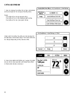
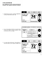
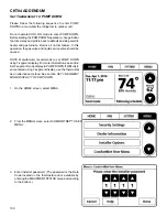
Page 100: ...alve and liquid service valve should be opened NOTE Manufacturer recommends to set PUMP DOWN using 7 segment display For more information see section Set 7 segment mode display to PUMP DOWN If difficulty is encountered using 7 segment display use the thermostat as an alternative method See section SET 7 SEGMENT MODE DISPLAY TO PUMP DOWN 1 On the HOME screen select MENU 2 From the MENU screen selec...

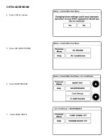
Page 101: ...CKT04 ADDENDUM 101 4 Select YES to continue 5 Select AIR CONDITIONER 6 Select MAINTENANCE 7 Select PUMP DOWN ...

Page 102: ...vice valve immediately 9 To terminate PUMP DOWN select PUMP DOWN screen again Press OFF Press DONE to terminate PUMP DOWN 10 Once PUMP DOWN is set navigate to HOME screen After finishing PUMP DOWN operation unit will stop automatically Unit will show error code E11 after the PUMP DOWN operation starts NOTE Refrigerant cannot be collected to the outdoor unit completely if the system is overcharged ...

Page 103: ...and Actual cooling provided RAF Requested CFM Actual CFM ATOF Outdoor Air Temperature Outdoor Fan speed OD air temperature OD Fan RPM DCT Discharge Temperature Outdoor Coil Temperature DLT Outdoor Liquid Temperature PSDST Only for DX20VC0 1AC or later revision ATPRM is shown in DX20VC0 AA AB revision Only for DX20VC0 1A C or later revision PSD is shown in DX20VC0 1AA AB revision F 2 Approximately ...

Page 104: ...able Options Comments Fault 1 FAULT 1 Most recent fault For display only Fault 2 FAULT 2 Next most recent fault For display only Fault 3 FAULT 3 Next most recent fault For display only Fault 4 FAULT 4 Next most recent fault For display only Fault 5 FAULT 5 Next most recent fault For display only Fault 6 FAULT 6 Least recent fault For display only Clear Faults CLEAR NO or YES Selecting YES clears t...

Page 105: ... selected in ACC User can choose the operation mode of humidifier HUM FAN SPD humidity airflow selection is only displayed if IND is selected in HUM and HUM is selected in ACC User can choose the indoor fan speed trim at the time of humidification Heater kit selection can also be done from this menu It is very important to select the correct heater kit value for normal operation of the system The ...

Page 106: ... the outdoor liquid temperature sensor readings Displays the low pressure sensor reading which is taken slightly upstream of the suction accumulator Only for DX20VC0 1AC or later revision ATPRM is shown in DX20VC0 1AA AB revision Only for DX20VC0 1AC or later revision PSD is shown in DX20VC0 1AA AB revision S T N E M M O C S N O I T P O E L B A I F I D O M R E S U M E T I U N E M B U S Reset Syste...

Page 107: ...r NO Selecting to default factory setting 1 2 C TR H 15 to 15 in 5 increments C TR I 15 to 20 in 5 increments 30 Full 3 C TR L 15 to 20 in 5 increments 30 Full 3 e l i o r p w o l r i a g n i l o o c e h t s t c e l e S D r o C B A L F R P L C y a l e d N O r e w o l b r o o d n i e h t s t c e l e S s d n o c e s 0 3 0 2 0 1 5 N O L C y a l e D N O l o o C y a l e d F F O r e w o l b r o o d n i ...

Reviews: