CKT04 ADDENDUM
106
A
IR
C
ONDITIONER
A
DVANCED
F
EATURE
M
ENU
SUBMENU ITEM
INDICATION/USER
MODIFIABLE OPTIONS
COMMENTS
.
y
r
o
t
s
i
h
t
l
u
a
f
e
h
t
s
r
a
e
l
c
"
S
E
Y
"
g
n
it
c
e
l
e
S
S
E
Y
r
o
O
N
s
tl
u
a
F
r
a
e
l
C
tl
u
a
f
C
A
t
n
e
c
e
r
t
s
o
M
1
t
l
u
a
F
tl
u
a
f
C
A
t
n
e
c
e
r
t
s
o
m
d
n
2
2
t
l
u
a
F
tl
u
a
f
C
A
t
n
e
c
e
r
t
s
o
m
d
r
3
3
t
l
u
a
F
tl
u
a
f
C
A
t
n
e
c
e
r
t
s
o
m
h
t
4
4
t
l
u
a
F
tl
u
a
f
C
A
t
n
e
c
e
r
t
s
o
m
h
t
5
5
t
l
u
a
F
tl
u
a
f
C
A
t
n
e
c
e
r
t
s
o
m
h
t
6
6
t
l
u
a
F
S
T
N
E
M
M
O
C
M
E
T
I
U
N
E
M
B
U
S
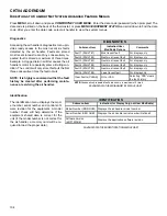
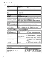
Time Stamp (TS)
Mode (MD)
Compressor Reduction Mode (CRM)
Requested and Actual % Demand (RAD)
Requested and Reported ID CFM (RAF)
Outdoor Air Temperature and Outdoor Fan
RPM (ATOF*)
Discharge Temperature and Outdoor Coil
Temperature (DCT)
Outdoor Liquid Temperature (DLT)
Pressure Sensor (PSDST**)
DIAGNOSTICS
STATUS
Provides compressor run time in hours.
Current system operation mode (COOLING, COOLING STARTUP, OIL RETURN, STOP).
Displays ON or OFF status. ON indicates that the reduction mode is operating and the compressor
is running at a lower speed than the cooling load would normally require.
Displays a 0-100% value, based on a ratio of the requested cooling demand to what the system is
actually providing.
Compares the requrested indoor airflow to what the indoor equipment has reported.
Displays the outdoor air temperature as well as the outdoor fan speed (RPM).
Displays the discharge temperature and outdoor coil temperature sensor readings.
Displays the outdoor liquid temperature sensor readings.
Displays the low pressure sensor reading which is taken slightly upstream of the suction
accumulator.
* Only for DX20VC0**1AC or later revision. ATPRM is shown in DX20VC0**1AA/AB revision.
** Only for DX20VC0**1AC or later revision. PSD is shown in DX20VC0**1AA/AB revision.
S
T
N
E
M
M
O
C
S
N
O
I
T
P
O
E
L
B
A
I
F
I
D
O
M
R
E
S
U
M
E
T
I
U
N
E
M
B
U
S
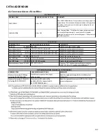
Reset System Setup Options to Factory
Defaults (SYS SETUP RESET)
.
s
g
n
it
t
e
s
t
l
u
a
f
e
d
y
r
o
t
c
a
f
o
t
u
n
e
m
s
i
h
t
s
t
e
s
e
r
"
S
E
Y
"
g
n
it
c
e
l
e
S
S
E
Y
r
o
O
N
.
e
s
u
e
r
u
t
u
F
A
/
N
T
N
E
R
R
U
C
X
A
M
T
E
S
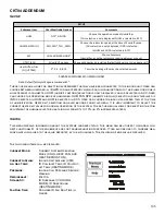
VERTICAL RISE
Same Level, Outdoor Lower, or
Indoor Lower
If the outdoor & indoor units are /- 15 ft. vertical distance,
select SAME LEVEL. If the outdoor unit is more
than 15 ft. below the indoor unit, select OUTDOOR LOWER. If
the outdoor unit is more than 15 ft. above the indoor unit, select
INDOOR L
BOOST MODE (BOOST MD)
ON or OFF
BOOST MD turns BOOST MODE OFF or ON. BOOST MODE
is ON by default. See BOOST MODE section of this manual for
more details.
BOOST MODE TEMPERATURE
(BOOST TEMP)
Always ON, 70,75,80,85,
90,95,100,105F
BOOST TEMP adjusts the activation temperature from 70° F to
105° F. An "Always ON" option is also available to permanently
engage BOOST MODE.
SYSTEM SETUP (SYS SETUP)
NOTE: BOOST MODE is applicable only for DX20VC0**1AC or later revision.
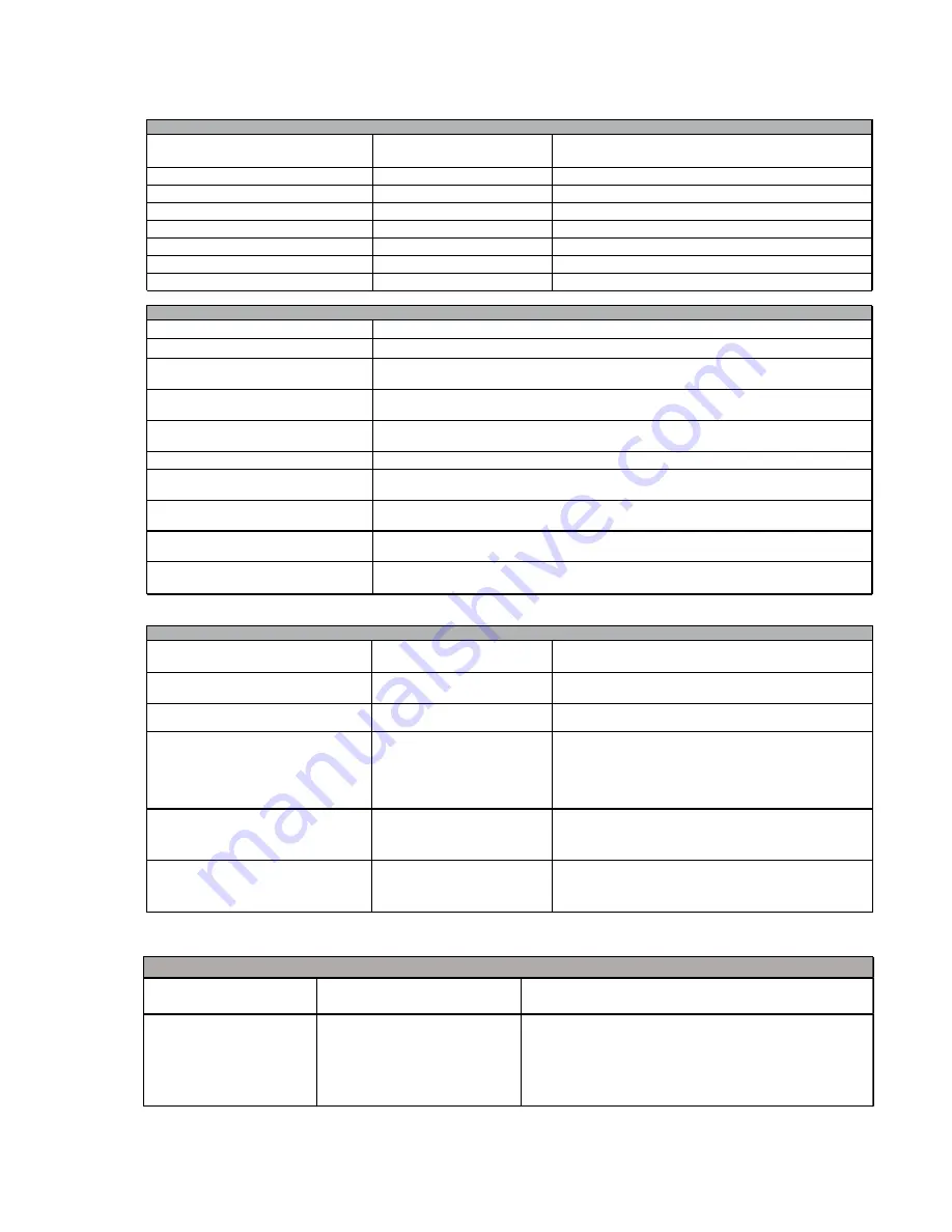
SUBMENU ITEM
INDICATION/USER
MODIFIABLE OPTIONS
COMMENTS
System Veri
fi
ca
�
on Test
(SYSTEM TEST)
ON or OFF
System Veri
fi
ca
�
on Test must be run a
�e
r installa
�
on.
This is approximately a 5-15 minute test. If the thermostat
is set to COOL mode, the system will enter CHARGE mode
upon comple
�
on, otherwise it will stop.
EQUIPMENT TEST (EQUIP TEST)


