SERVICING
28
NOTE
: The use of a heat shield when brazing is recom-
mended to avoid burning the serial plate or the finish on the
unit. Heat trap or wet rags should be used to protect heat
sensitive components such as stop valves, sensors TXV
and filters.
Copper to Copper Joints
- Sil-Fos used without flux (alloy
of 15% silver, 80% copper, and 5% phosphorous). Recom-
mended heat 1400°F.
Copper to Steel Joints
- Silver Solder used without a flux
(alloy of 30% silver, 38% copper, 32% zinc). Recommended
heat - 1200°F.
S-101 LEAK TESTING (NITROGEN OR NITROGEN-
TRACED)
WARNING
TO AVOID THE RISK OF FIRE OR EXPLOSION, NEVER USE OXY-
GEN, HIGH PRESSURE AIR OR FLAMMABLE GASES FOR LEAK
TESTING OF A REFRIGERATION SYSTEM.
WARNING
TO AVOID POSSIBLE EXPLOSION, THE LINE FROM THE NITRO-
GEN CYLINDER MUST INCLUDE A PRESSURE REGULATOR AND
A PRESSURE RELIEF VALVE. THE PRESSURE RELIEF VALVE
MUST BE SET TO OPEN AT NO MORE THAN 150 PSIG.
Pressure test the system using dry nitrogen and soapy wa-
ter to locate leaks. If you wish to use a leak detector, charge
the system to 10 PSIG using the appropriate refrigerant then
use nitrogen to finish charging the system to working pres
-
sure, then apply the detector to suspect areas. If leaks are
found, repair them. After repair, repeat the pressure test. If
no leaks exist, proceed to system evacuation.
S-102 EVACUATION
WARNING
REFRIGERANT UNDER PRESSURE!
FAILURE TO FOLLOW PROPER PROCEDURES MAY CAUSE
PROPERTY DAMAGE, PERSONAL INJURY OR DEATH.
IMPORTANT NOTE:
Because of the potential damage to
compressors, do not allow suction pressure at service valve
to drop below 5 PSIG when pumping unit system down for
repair. Outdoor section, depending on line set length and
amount of charge in system, may not be able to hold the
entire system charge.
This is the most important part of the entire service proce-
dure. The life and efficiency of the equipment is dependent
upon the thoroughness exercised by the serviceman when
evacuating air (non-condensables) and moisture from the
system.
Air in a system causes high condensing temperature and
pressure, resulting in increased power input and reduced
performance.
Moisture chemically reacts with the refrigerant oil to form
corrosive acids. These acids attack motor windings and
parts, causing breakdown.
The equipment required to thoroughly evacuate the sys-
tem is a high vacuum pump, capable of producing a vacu-
um equivalent to 25 microns absolute and a thermocouple
vacuum gauge to give a true reading of the vacuum in the
system.
NOTE
: Never use the system compressor as a vacuum
pump or run when under a high vacuum. Motor damage
could occur.
WARNING
DO NOT FRONT SEAT THE SERVICE VALVE(S) WITH THE COM-
PRESSOR OPEN, WITH THE SUCTION LINE OF THE COMPRES-
SOR CLOSED OR SEVERELY RESTRICTED.
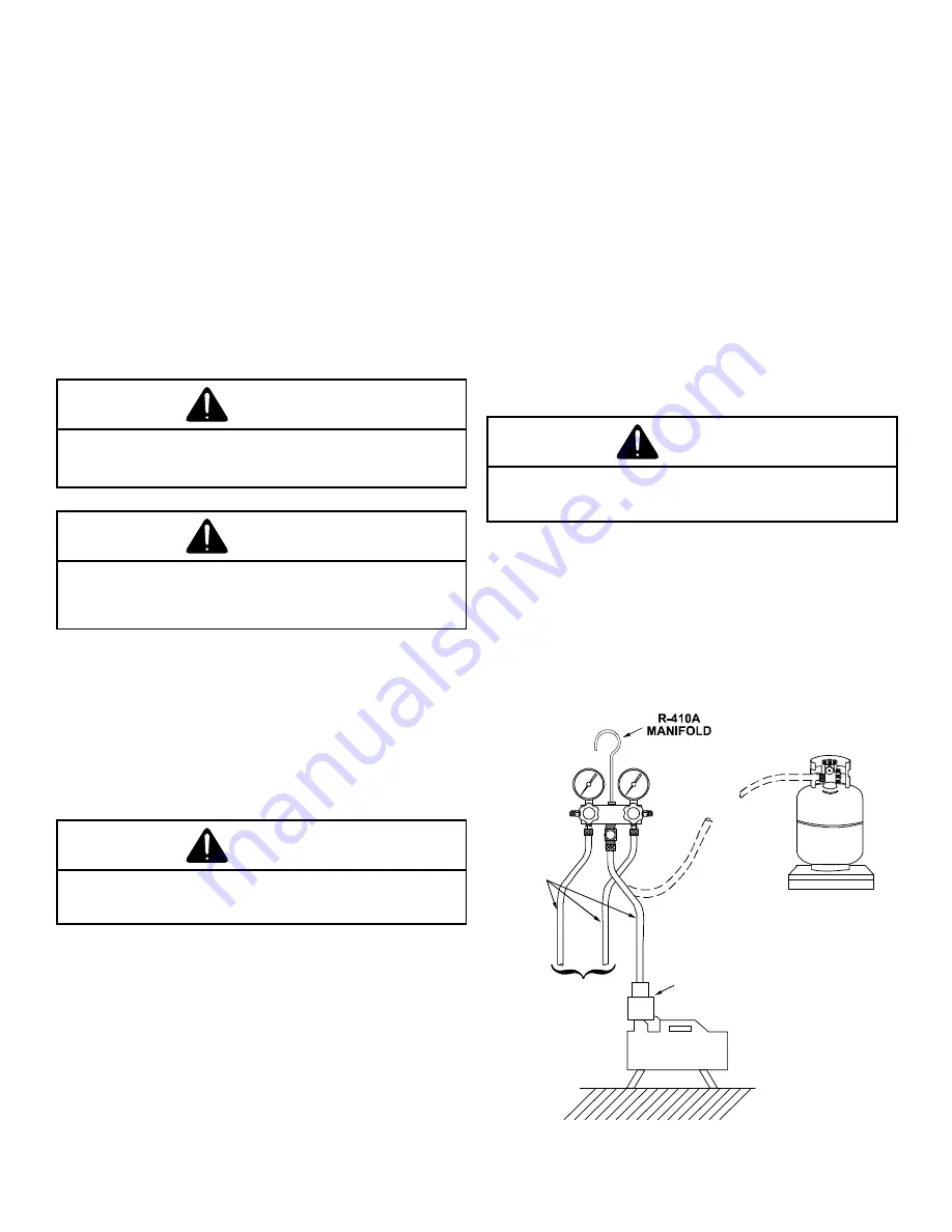
1. Connect the vacuum pump, vacuum tight manifold set
with high vacuum hoses, thermocouple vacuum gauge
and charging cylinder as shown.
2.
Start the vacuum pump and open the shut off valve to the
high vacuum gauge manifold only. After the compound
gauge (low side) has dropped to approximately 29 inch-
es of vacuum, open the valve to the vacuum thermocou-
ple gauge. See that the vacuum pump will blank-off to a
maximum of 25 microns. A high vacuum pump can only
produce a good vacuum if its oil is non-contaminated.
LOW SIDE
GAUGE
AND VALVE
HIGH SIDE
GAUGE
AND VALVE
TO
UNIT SERVICE
VALVE PORTS
VACUUM PUMP
VACUUM PUMP
ADAPTER
800 PSI
RATED
HOSES
CHARGING
CYLINDER
AND SCALE
EVACUATION


