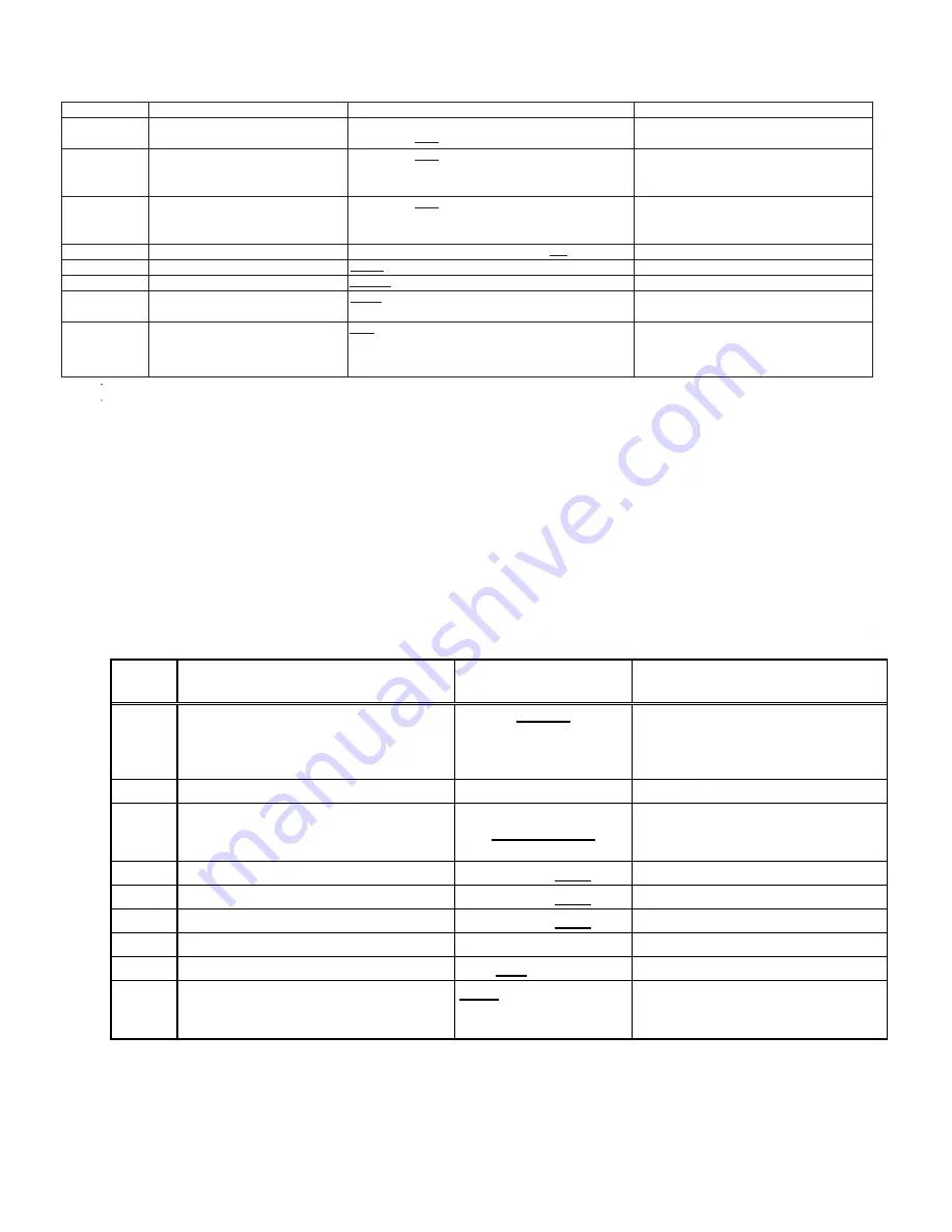
7 SEGMENT DISPLAY-OUTDOOR UNIT
66
Se
tt
ing
No.
s
e
t
o
N
n
a
m
e
c
i
v
r
e
S
/
r
e
ll
a
t
s
n
I
g
n
it
t
e
S
s
t
n
e
t
n
o
C
1
Maximum Defrost Interval
0: 30min.
1: 60min.
2: 90min.
3: 120min.
e
s
U
e
r
u
t
u
F
A
/
N
t
n
e
rr
u
C
m
u
m
ix
a
M
t
e
S
2
3
Vertical Rise
0:Same Level
1:Outdoor Lower
2:Indoor Lower
4
System Verification Test (System Test)
0:ON
1:OFF
8
Pump Down
0:ON
1:OFF
9
Charge Mode
0:ON
1:OFF
10
Maximum Compressor RPS for Cooling
*
12
BOOST MODE Selection
0:ON
1:OFF
13
BOOST MODE Temperature
0:105F
, 1:100F, 2:95F, 3:90F,
4:85F, 5:80F, 6:75F, 7:70F,
8:Always ON
Depends on tonnage. Can adjust compressor RPS in each 0.5 RPS
NOTES:
•
Parameters as per factory setting are highlighted in bold and underlined.
• BOOST MODE is applicable only for DX20VC0**1AC or later revision.
Se
tt
ing No.
Contents
Installer/Serviceman Notes
1
Cool Airflow Trim High
*1, *2
0: -15%
1: -10%
2: -5%
3: 0%
4: 5%
5: 10%
6: 15%
%
5
1
-
:
0
t
n
I
m
ir
T
w
o
lf
ri
A
l
o
o
C
2
1: -10%
2: -5%
3: 0%
4: 5%
5: 10%
6: 15%
7: 20%
8: 30%
9: Full
(Max)
*3
%
5
1
-
:
0
w
o
L
m
ir
T
w
o
lf
ri
A
l
o
o
C
3
1: -10%
2: -5%
3: 0%
4: 5%
5: 10%
6: 15%
7: 20%
8: 30%
9: Full
(Max)
*3
C
:
2
B
:
1
A
:
0
e
lif
o
r
P
l
o
o
C
4
3: D
5
Cool Fan ON Delay
0: 5sec .
1: 10sec.
2: 20sec.
3: 30sec.
6
Cool Fan OFF Delay
0: 30sec.
1: 60sec.
2: 90sec.
3: 120sec.
7
Dehumidification Select
*4
0: STD
1: OFF
2: A
3: B
4: C
13
Airflow Trim Offset
*1
, *2
0: 0%
o
t
%
5
.
2
g
n
i
d
d
a
y
b
g
n
it
t
e
s
m
ir
t
l
a
n
o
it
i
d
d
a
r
o
f
d
e
s
U
%
5
.
2
+
:
1
basic airflow trim setting. This setting affects all trim
settings except
+15% High (cooling or heating).
SCREEN 3 (SETTING MODE 1)
Se
tt
ing
NOTE: Parameters as per factory se
�
ng are highlighted in bold and underlined.
The speci
fi
ca
�
on of DX20VC0241BD, 0361BC, 0481BC and 0601BC or earlier models are di
ff
erent from this speci
fi
ca
�
on.
For details, see the Installa
�
on Manual or Service Manual that matches the Major and Minor revision of model name.
*1 DX20VC0601* with D*96VC0804C, D*97MC0804C and DM80VC0804C combina
�
on trim more than 5% se
�
ngs are invalid.
Trimmed up CFM makes miss matching error.
*2 Depending on the connected indoor unit, there are restric
�
ons on the posi
�v
e side Trim se
�n
g.
If you want to change the Cool Air
fl
ow Trim to posi
�v
e side, be sure to con
fi
rm the Air
fl
ow Trim restric
�on
s in the latest indoor unit installa
�
on manual.
The latest manual can be obtained from the website “DAIKIN CITY (Installa
�
on Manual/Unitary Split System)” or “PartnerLink(InfoFinderPlus/Literature)”. [DAIKIN CITY URL]
h
�
ps://www.daikincity.com/Library/ [PartnerLink URL]
h
�
ps://partnerlinkmarke
�
ng.goodmanmfg.com/goodman/info-
fi
nder-plus
*3 The Inverter system uses lower compressor speed and lower indoor unit CFM to op
�
mize system performance.
To obtain 100% CFM for home circula
�
on, use full Trim se
�
ng instead of Int/Low speed.
This is recommended for applica
�ons
with unusually cold return temperatures such as basements.
*4 Please refer to the page of "D
EHUMIDIFICATION
S
ELECT
" for details of this func
�
on.
SCREEN 4 (SETTING MODE2)


